Vacuum arc plasma thrusters with inductive energy storage driver

a technology of inductive energy storage and vacuum arc plasma, which is applied in the direction of machines/engines, mechanical equipment, manufacturing tools, etc., to achieve the effects of low mass, high resistivity, and effective “throttle”

a technology of inductive energy storage and vacuum arc plasma, which is applied in the direction of machines/engines, mechanical equipment, manufacturing tools, etc., to achieve the effects of low mass, high resistivity, and effective “throttle”

US20070045248A1Inactive Publication Date: 2007-03-01KRISHNAN MAHADEVAN

Image

  • Vacuum arc plasma thrusters with inductive energy storage driver
  • Vacuum arc plasma thrusters with inductive energy storage driver
  • Vacuum arc plasma thrusters with inductive energy storage driver

Examples


Embodiment Construction

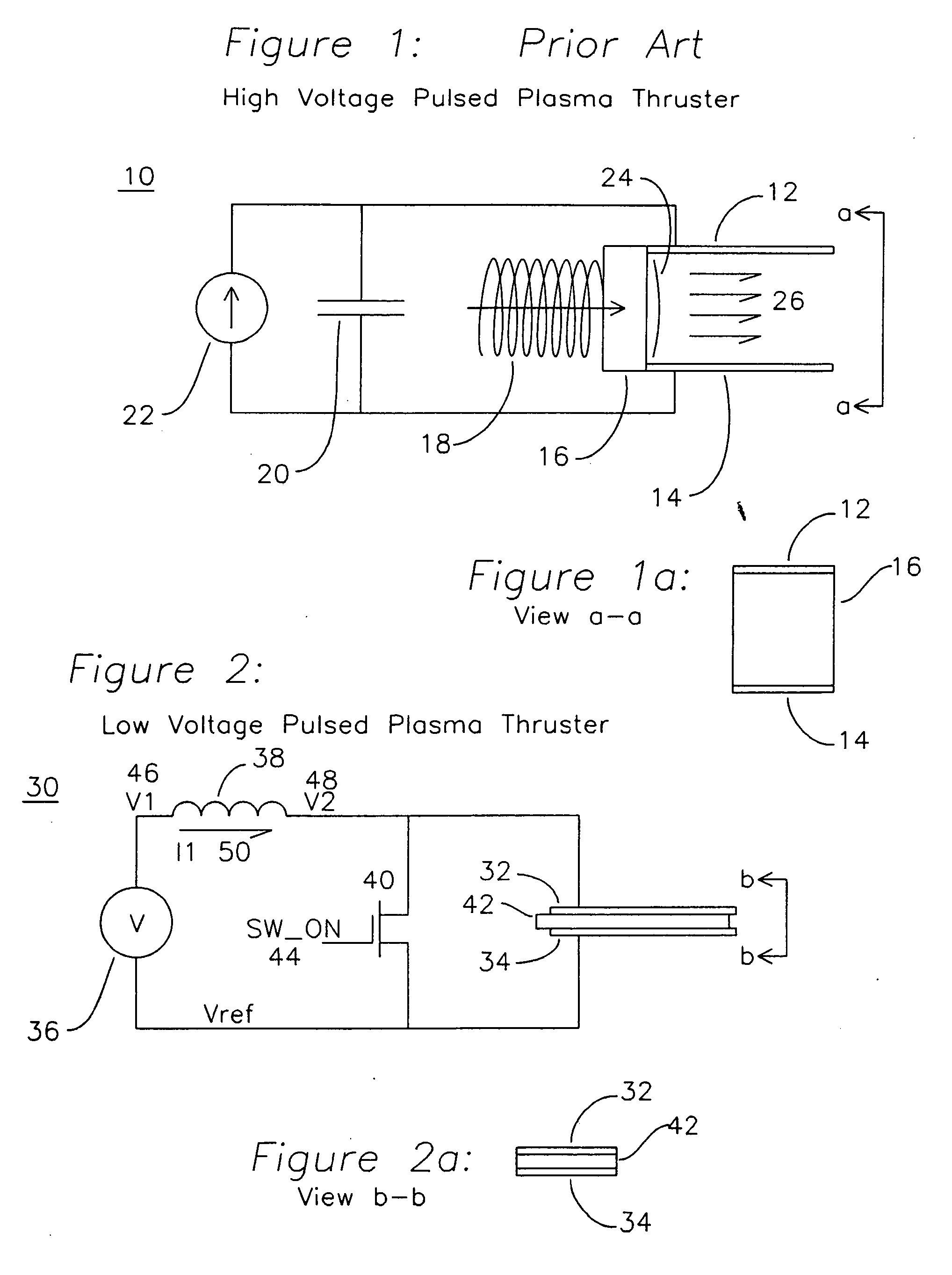
[0028] The present letters patent describes a low mass vacuum arc thruster system using a PPU that uses inductive energy storage (IES) as shown in FIG. 1. Since no high voltage energy storage capacitors are needed for this circuit, the driver is compact, low-mass and has long lifetime. The mass of this system can be as low as ˜60 g for the driver and ˜30 g for the arc source.

[0029]FIG. 1 shows a circuit diagram and mechanical diagram for a prior art pulsed plasma thruster. A current source or current limited voltage source 22 is applied to a storage capacitor 20. The capacitor 20 provides charge to a positive anode electrode 12 and a negative cathode electrode 14 which are separated by an insulator 16 which also acts as a propellant, and is made of a material such as PTFE. When the voltage across the capacitor 20 reaches a voltage sufficient to reach dielectric breakdown, a plasma arc 24 develops, and the high plasma temperature causes the insulator and propellant 16 to emit partic...


PUM

PropertyMeasurementUnit
Electrical conductivityaaaaaaaaaa
Energyaaaaaaaaaa

Abstract

An apparatus for producing a vacuum arc plasma source device using a low mass, compact inductive energy storage circuit powered by a low voltage DC supply acts as a vacuum arc plasma thruster. An inductor is charged through a switch, subsequently the switch is opened and a voltage spike of Ldi / dt is produced initiating plasma across a resistive path separating anode and cathode. The plasma is subsequently maintained by energy stored in the inductor. Plasma is produced from cathode material, which allows for any electrically conductive material to be used. A planar structure, a tubular structure, and a coaxial structure allow for consumption of cathode material feed and thereby long lifetime of the thruster for long durations of time.

Description

[0001] This invention was made with Government support under contract F29601-02-C-0016 awarded by the Air Force Research Laboratory and contract NAS3-02047 by the NASA Glenn Research Center. The Government has certain rights in this invention.FIELD OF THE INVENTION [0002] The invention pertains to the use of inductive energy storage power processing units for ignition and / or driving in conjunction with plasma sources that are especially tailored for vacuum arc plasmas used in propulsion devices. The stored inductive energy may be used to generate a plasma which may be used to propel or provide thrust control for a device in a gravitation-free environment, or in a fixed orbit about a planet in an atmospheric vacuum, such as outer space. BACKGROUND OF THE INVENTION [0003] Pulsed Plasma Thrusters (PPT) are used to provide periodic pulses of thrust for satellites in space. Prior art high voltage PPTs were constructed from coaxial electrodes with a PTFE propellant in a coaxial configurat...

Claims


Application Information

Patent Timeline
01 Mar 2007
Publication
US20070045248A1
IPC
B23K9/00; B23K9/02
CPC
H05H1/54; F03H1/0087
Inventors
SCHEIN, JOCHEN; GERHAN, ANDREW N.