Ink-jet image forming method

a technology of image forming and inkjet printing, which is applied in the direction of inks, coatings, instruments, etc., can solve the problems of image storage stability, image fading, image storage stability, etc., and achieve excellent weather resistance, high density, and high gloss.

Inactive Publication Date: 2007-03-08
KONICA MINOLTA PHOTO IMAGING
View PDF4 Cites 17 Cited by
  • Summary
  • Abstract
  • Description
  • Claims
  • Application Information

AI Technical Summary

Benefits of technology

[0028] According to the present invention, it is possible to provide a method of forming an ink-jet image which exhibits excellent weather resistance, and a highly glossy and highly dense color image without a decrease of ink absorbability, and also to provide a method by which initial filming capability contributing to ozone gas resistance and tectile sense of glossiness, and storage stability such as reduction of layer destruction over long-term storage under an environment of high temperature and high humidity.

Problems solved by technology

An ink-jet print system is inferior, specifically in image storage stability and feeling of glossiness, compared to silver halide photography.
Specifically problematic in image storage stability is ozone fading due to ozone and NOx in the atmosphere.
However, to achieve high ink absorbability required in recent high speed printers, a so-called porous type ink-jet recording medium is essential as an ink-jet recording medium, but this porous type ink-jet recording medium has the drawback that gases can easily penetrate into the porous layer.
However, the methods incorporating the above Patent Documents, can provide a certain degree of desired effects with respect to oxidizing gas resistance, but it was learned that these methods have a serious drawback of significantly reduced gas resistance because of layer destruction together with lowered glossiness due to effects of heat and humidity over long term storage, even under a benign environment.
Further, high glossiness similar to that of silver halide prints can be obtained by covering the surface of the porous type recording medium with a resin layer, however, it was learned that the transparency is drastically decreased due to aggregation of coloring agents and microscopic resin particles, resulting in decreased coloring.

Method used


Image

  • Ink-jet image forming method
  • Ink-jet image forming method
  • Ink-jet image forming method

Examples


example 1

Preparation of Ink Set (Ink Composition)

Preparation of Ink Set 1

Preparation of Color Ink Set 1

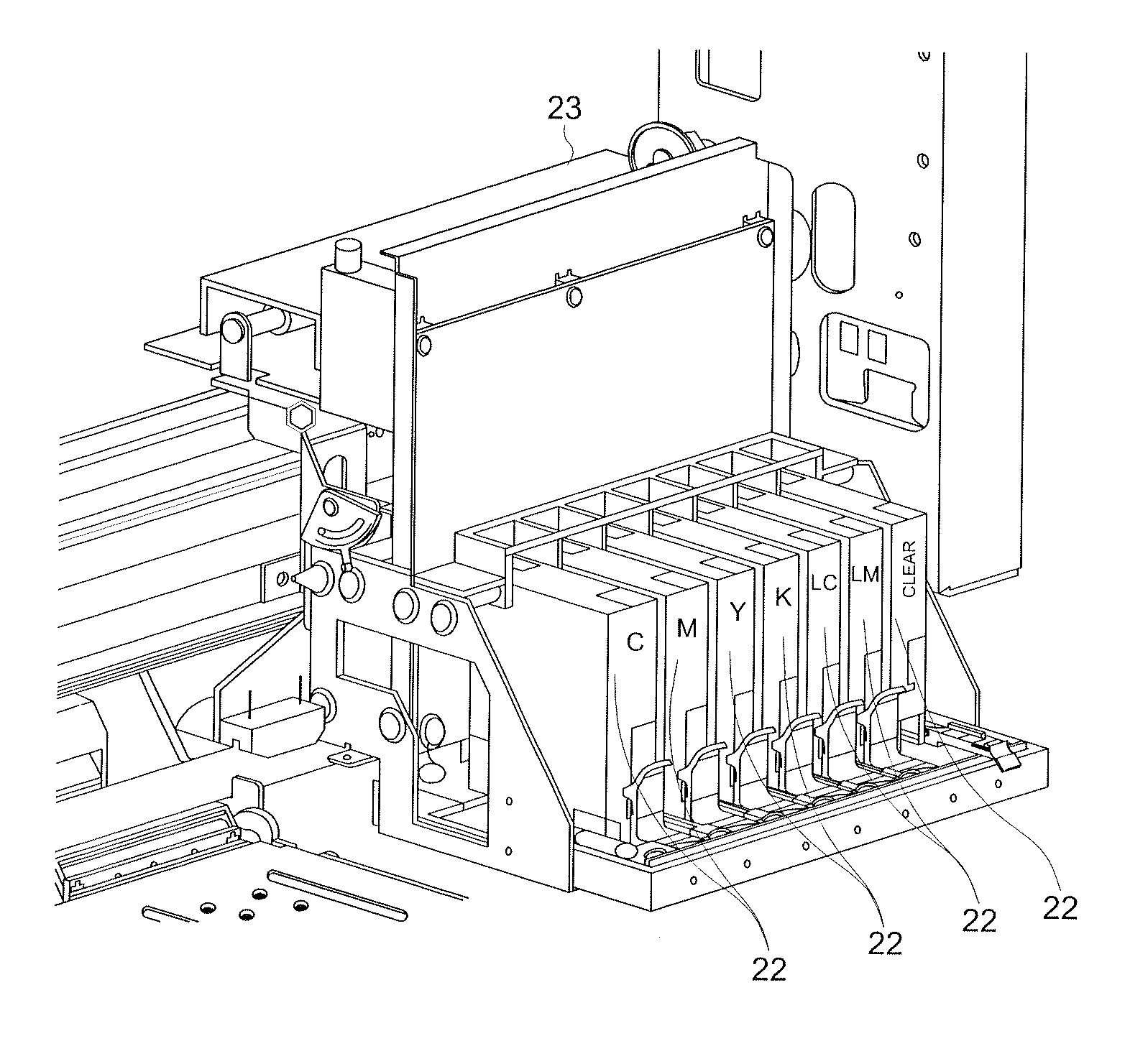
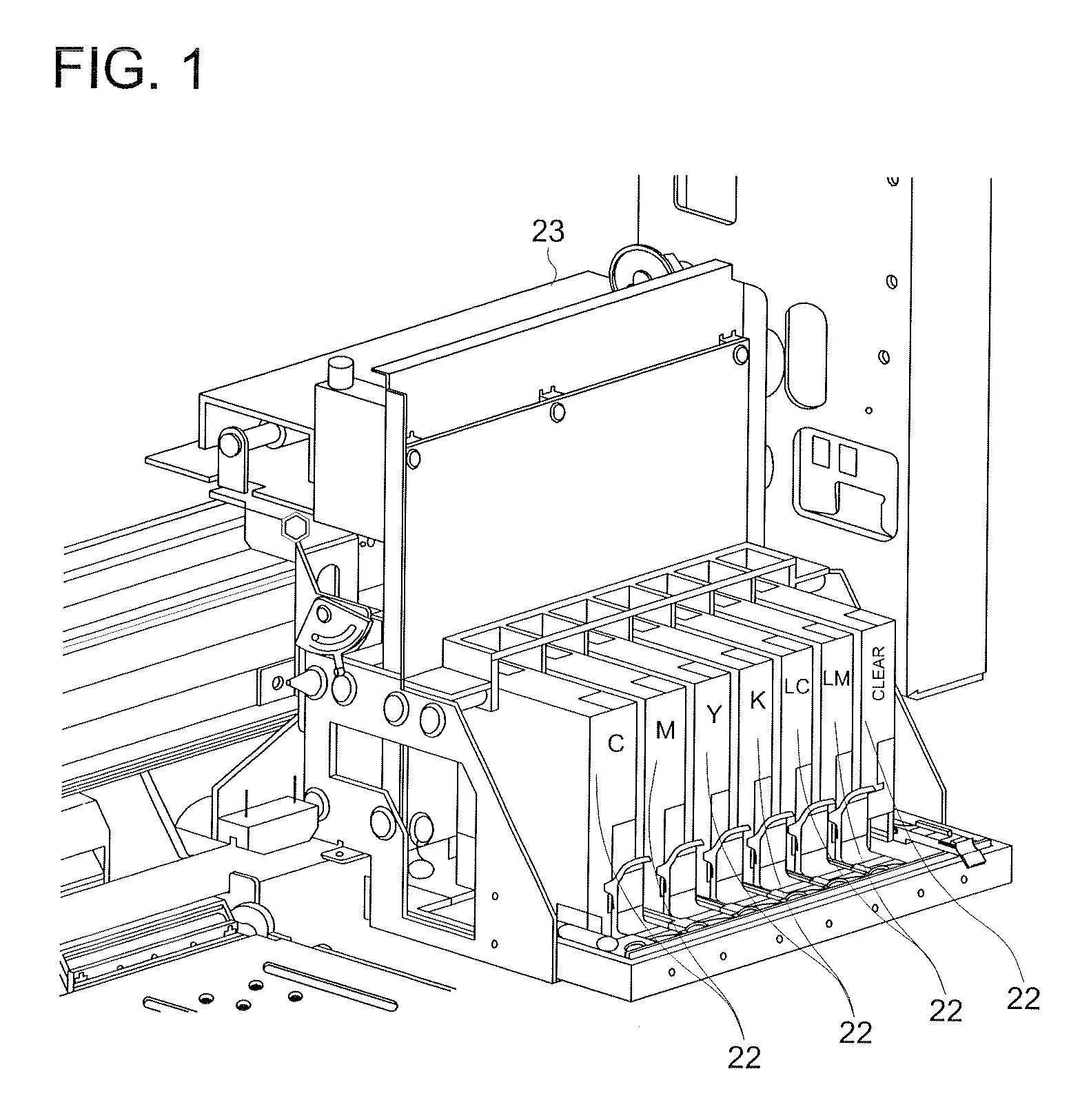
[0223] Color Ink Set 1 was prepared as follows. Color Ink Set 1 was composed of six colors of Dark Inks of Yellow Ink (Y), Magenta Ink (M), Cyan Ink (C), and Black Ink (K), and Light Inks of Light Magenta Ink (Lm), and Light Cyan Ink (Lc). After each ink was mixed as follows, pH was adjusted within the range of 9.0±0.3 by dripping of triethanolamine. Subsequently, the ink was filtered employing a 3 μm membrane filter, and transferred into an empty cartridge. Preparation of Dark Color Ink: Yellow Ink (Y)

Dye: Direct Yellow 863.0weight %Diethylene glycol13weight %Glycerine10weight %Triethylene glycol monobutyl ether5.0weight %Microscopic resin particles1.5weight %[SX105A: produced by Zeon Corp.,being a styrene-butadienecopolymer resin (namely asanion modified latex), exhibitingTg of 0° C., an averageparticle diameter of109 nm] (in solidcontent equivalent)Surface active agent (Surfynol1...

example 2

Preparation of Ink Set

Preparation of Ink Sets 6-14

[0284] Ink Sets 6-14 were prepared in the same manner as preparation of Ink Set 1 described in Example 1, except that the microscopic resin particles [being SX1105A, produced by Zeon Corp., and being a styrene-butadiene copolymer resin (anionic modified latex), exhibiting a Tg of 0° C. and an average particle diameter of 109 nm] employed in Color Ink Set 1 and Clear ink 1, was replaced with each of the microscopic resin particles described in Table 2.

[0285] In addition, the details of each type of microscopic resin particle, described in Table 2 with abbreviated names, is shown below.

[0286] SF 300: an anionic modified urethane resin, exhibiting a Tg of −42° C. and an average particle diameter of 91 nm, produced by Dai-Ichi Kogyo Seiyaku Co., Ltd.

[0287] SR 110: an anionic modified styrene-butadiene copolymer resin, exhibiting a Tg of −27° C. and an average particle diameter of 116 nm, produced by Nippon A&L Inc.

[0288] A 2510: ...

example 3

Preparation of Ink-Jet Recording Medium

Preparation of Recording Medium 7

Preparation of Outermost Layer Coating Composition 1

[0297] Silica Dispersion Liquid 3 was prepared in the same manner as Silica Dispersion Liquid 1 described in Example 1, except that Cationic Polymer (P-1) was omitted. An aqueous solution containing this Silica Dispersion Liquid 3 at a solid content of 2%, polyvinyl alcohol (being PVP235, produced by Kuraray Co., Ltd.) at a solid content of 0.2%, and a surface active agent (being Olfine E1010, produced by Nisshin Chemical Industry Co., Ltd.) of 0.3% as an active ingredient, was prepared, and was designated as Outermost Layer Coating Composition 1.

Preparation of Recording Medium

[0298] Onto the 4th layer of the ink absorptive layer of Recording Medium 1 described in Example 1, pure water was provided to fill the voids with water, after which Outermost Layer Coating Composition 1, prepared as above, was applied employing a wire-bar method so that the soli...


PUM

PropertyMeasurementUnit
diameteraaaaaaaaaa
diameteraaaaaaaaaa
glass transition temperature Tgaaaaaaaaaa

Abstract

A method of forming an ink-jet image comprising the steps of: i. ejecting ink compositions from an ink-jet head onto a recording medium; and ii. forming an image, wherein a) the recording medium is a porous type medium having a porous ink absorbing layer on a non-water absorptive support, b) the ink-jet head has a plurality of nozzles which eject more than two ink compositions respectively, and one ink composition is a clear ink, and one ink composition is a color ink, c) the clear ink contains water dispersible microscopic resin particles having an average diameter of 10-200 nm of more than 1 weight %, and d) pH of the ink compositions is 6.5-11.0, and an absolute value of a difference, between an ink composition pH and film surface pH of the recording medium, is less than 4.0.

Description

[0001] This application is based on Japanese Patent Application No. 2005-254555 filed on Sep. 2, 2005, in Japanese Patent Office, the entire content of which is hereby incorporated by reference. FIELD OF THE INVENTION [0002] The present invention relates to an ink-jet image forming method in which a clear ink, containing microscopic resin particles, is ejected onto a porous type ink-jet recording medium with an ink-jet recording method, and specifically in detail, relates to an ink-jet image forming method to form a highly glossy and highly dense color image exhibiting high weather resistance. BACKGROUND OF THE INVENTION [0003] An ink-jet print system is inferior, specifically in image storage stability and feeling of glossiness, compared to silver halide photography. Specifically problematic in image storage stability is ozone fading due to ozone and NOx in the atmosphere. Means to decrease ozone fading are described in, for example, Unexamined Japanese Patent Application Publicati...

Claims


Application Information

Patent Timeline
Patent Type & Authority Applications(United States)
IPC IPC(8): B41J2/01B41J2/17G01D11/00B05D1/26B41M5/00C09D11/00C09D11/322C09D11/328C09D11/40
CPCC09D11/30B41J2/2114
Inventor ITOH, HIROAKINOJIMA, TAKAHIKO
Owner KONICA MINOLTA PHOTO IMAGING
Why Eureka
Try Eureka