
Preparation of catalyst and use for high yield conversion of methane to ethylene

Inactive Publication Date: 2007-03-08
HRD CORP
View PDF0 Cites 13 Cited by
  • Summary
  • Abstract
  • Description
  • Claims
  • Application Information

AI Technical Summary

Benefits of technology

[0015] By periodically adding a halogen source to the OCM reactor over the course of the oxidative coupling reaction. the activity of the catalyst can be maintained over time.

Problems solved by technology

One of the most outstanding problems in heterogeneous catalysis concerns its use in the partial oxidation of methane to form more reactive chemicals such as ethane, ethylene and other aliphatic hydrocarbons.

Method used


Image

  • Preparation of catalyst and use for high yield conversion of methane to ethylene
  • Preparation of catalyst and use for high yield conversion of methane to ethylene
  • Preparation of catalyst and use for high yield conversion of methane to ethylene

Examples


example 1

Oxidative Coupling of Methane

[0046] A variety of catalysts were prepared using the sol-sol methodology of the present invention. Different alkali earth metals were applied for use in a direct conversion reaction for the production of ethylene from methane. The catalysts were prepared employing the basic perovskite crystal formula, ABTiO3, so as to determine the optimum perovskite catalyst which is capable of reproducibly producing the greatest yield of ethylene. Combinations were tried including A=tin (Sn) and wherein B was selected from=Ca,Sr,Ba or combinations thereof.

[0047] Evaluations of this formulation were undertaken in the range of Ba ((1-2 moles−x)+TiO2 ((1 mole))+SnCl2(x) where x ranges between 0.09 and 0.1 moles, or 0.95 moles Barium per mole of TiO2 to 0.05 moles SnCl2.

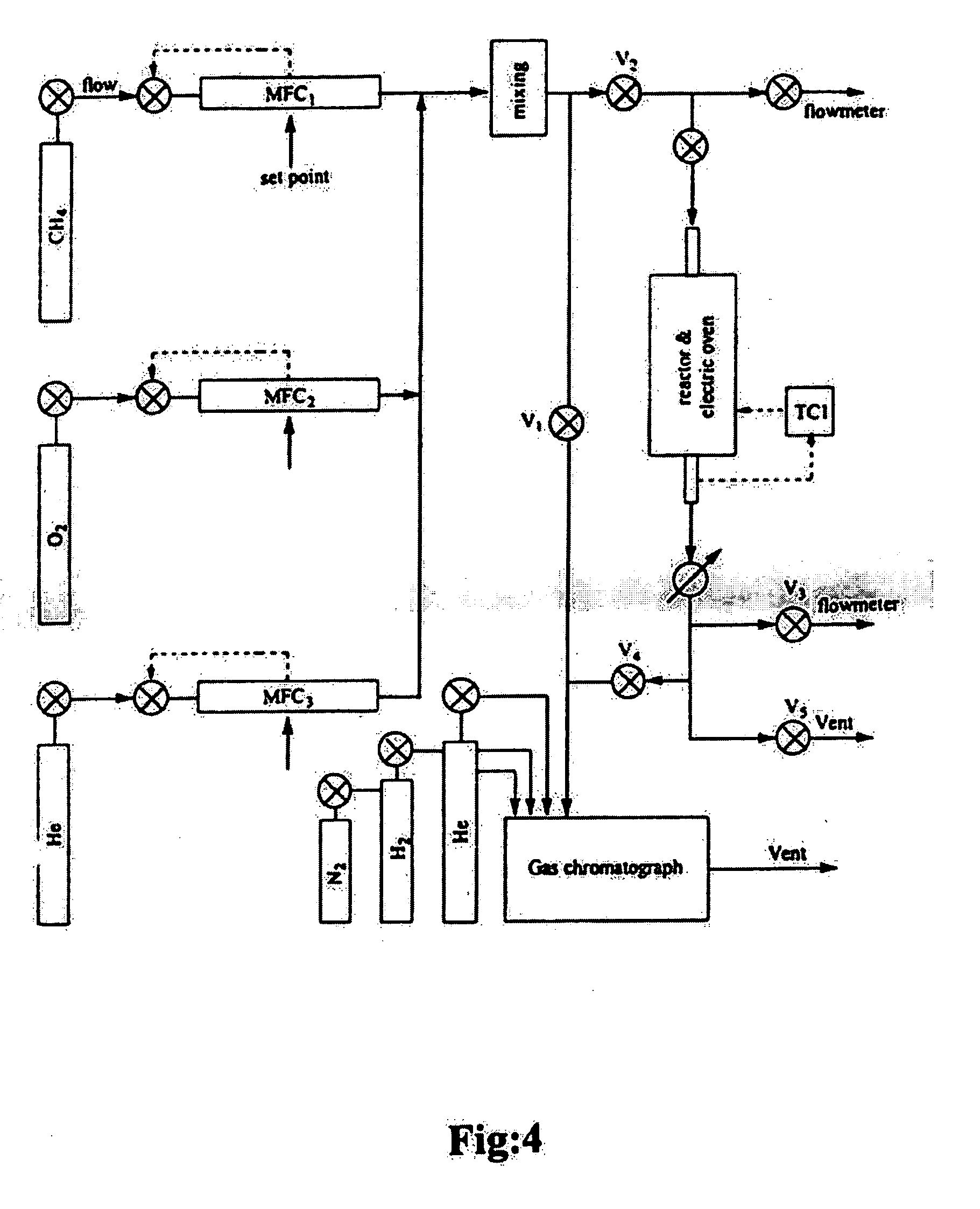
[0048] With reference to FIG. 4, the reactor experiments were carried out in a flow fixed-bed quartz reactor having a diameter of 10 mm at a temperature ranging from between about 500° C.-about 1000° C....

example 2

Pilot Scale Oxidative Coupling of Methane: Effect of Halogen Addition

[0054] In this example, and in Example 3, OCM was performed using a pilot reactor with approximately 30.5 grams of a catalyst prepared from a mixture of Barium carbonate, Tin chloride and Titanium oxide, combined in a ratio of 39.3 grams; 11.4 grams; 19.2 grams. The resulting catalyst was then pelletized under 5.5 tons / cm3 and crushed into particles of between 1.96-3.96 mm diameter.

[0055] A model SS316 reactor tube having dimensions of 25 mm (O.D., 21 mm I.D.) by 490 mm in length was fitted with a quartz liner, and quartz packing, and the catalyst packed towards the middle of the reactor tube without dilution, as shown in FIG. 7 (illustrating top gas feed). The effects of both bottom and top gas feed injection were evaluated; the best results (Table 2) were achieved using bottom gas feed. The top and bottom portions of the reactor were packed with quartz particles of diameter ranging from 1.98-3.96 mm.

[0056] In ...

example 3

[0063] For this example, the same catalyst as used in Example 2 was employed, but not diluted; no halogen was added to the reactor.

[0064] For this example, the parameters were as follows: [0065] Methane / Oxygen / Nitrogen molar ratio of inlet gas: CH4:O2:N2 was 2:1:8. [0066] GHSV=5123; [0067] WHSVCI=0.44; [0068] Quartz-lined reactor, no CCl4 added.


PUM

PropertyMeasurementUnit
temperatureaaaaaaaaaa

Abstract

A perovskite catalyst is prepared using a ceramic sol-sol methodology comprising preparing slurry in water of an alkaline earth metal salt, a powdered metal salt and a powdered transition metal oxide, adding a polymeric binder to form a paste, drying and comminuting the paste into a powder and heating the powder with a temperature profile to calcination temperatures. In one embodiment the slurry is formed of titanium oxide with barium carbonate and tin chloride in deionized water, and more specifically by a mixture according to Ba (1−0.05x)+TiO2+SnCl2(0.05x) where x is in moles. The perovskite catalyst is preferably used in a process for oxidative coupling of methane. Catalyst performance is enhanced through the addition of halides to the feed gas in the reaction.

Description

CROSS-REFERENCES TO RELATED APPLICATIONS [0001] This application is a division of U.S. patent application Ser. No. 10 / 833,735, filed 28 Apr. 2004, which application claims priority under 35 U.S.C. §119 to Canadian patent application serial no. 2,427,722, filed 29 Apr. 2003, entitled Preparation of Catalyst and Use For High Yield Conversion of Methane to Ethylene, the inventor being Ebrahim Bagherzadeh, an inventor of the present application, and assigned to the assignees of this application, HRD Corp., Houston, Tx. and National Petrochemical Company, Petrochemical Research and Technology Company of Tehran, Iran.FIELD OF THE INVENTION [0002] The invention relates to the synthesis of higher hydrocarbons from methane. More particularly, the invention relates to methods for forming perovskite catalysts capable of high conversion yield. BACKGROUND OF THE INVENTION [0003] One of the most outstanding problems in heterogeneous catalysis concerns its use in the partial oxidation of methane t...

Claims


Application Information

Patent Timeline
Patent Type & Authority Applications(United States)
IPC IPC(8): C07C17/26C07C2/58B01J21/06B01J23/00B01J23/02B01J23/14B01J27/08B01J35/00B01J37/00B01J37/08C01G23/00C04B35/634C04B35/636C07C2/84
CPCB01J21/063Y10S502/525B01J23/02B01J23/14B01J27/08B01J35/0006B01J37/0018B01J37/08B01J2523/00C01G23/003C01G23/006C01P2002/34C01P2002/72C04B35/63424C04B35/636C04B2235/3208C04B2235/3215C04B2235/3236C07C2/84C07C2521/06C07C2523/02C07C2527/06C07C2527/10B01J23/002C07C11/04B01J2523/12B01J2523/25B01J2523/47B01J2523/43B01J2523/11B01J2523/23B01J2523/24B01J2523/22Y02P20/52Y02P20/141B01J35/19
Inventor BAGHERZADEH, EBRAHIMHASSAN, ABBASHASSAN, AZIZ
Owner HRD CORP
Learn More