
Compression and injection molding applications utilizing glass fiber bundles

a technology of glass fiber bundles and injection molding, which is applied in the direction of drying machines with progressive movements, lighting and heating apparatus, furnaces, etc., can solve the problems of high manufacturing cost of wet chopped fiber bundles, and achieve the effect of increasing the speed at which glass fiber bundles can be produced, improving throughput, and speeding up the speed of speed

Inactive Publication Date: 2007-03-15
OCV INTELLECTUAL CAPITAL LLC
View PDF23 Cites 27 Cited by
  • Summary
  • Abstract
  • Description
  • Claims
  • Application Information

AI Technical Summary

Benefits of technology

[0014] It is an advantage of the present invention that the chopped glass fiber bundles may be formed at a faster rate of speed. Increasing the rate of speed that the chopped glass fiber bundles can be produced permits for a higher throughput and additional product that can be sold to customers.
[0015] It is another advantage of the present invention that the chopped glass fiber bundles can be formed with low manufacturing costs because the wet glass fibers can be dried in bulk.
[0016] It is yet another advantage of the present invention that the chopped glass fibers bundles are formed in one step and dried in a container that may then be shipped to mat making facilities or to customers that use the chopped glass fibers in compression or injection molding applications.
[0017] It is a further advantage that the chopped glass fiber bundles may be used directly in compression or injection molding applications without modification to the bundles.

Problems solved by technology

Dried chopped fiber strands are typically more expensive to manufacture than wet chopped strands because the dry fibers are generally dried and packaged in separate steps before being chopped.

Method used


Image

  • Compression and injection molding applications utilizing glass fiber bundles
  • Compression and injection molding applications utilizing glass fiber bundles
  • Compression and injection molding applications utilizing glass fiber bundles

Examples


example 1

Formation of Dry Chopped Glass Fiber Bundles

[0072] The sizing formulations set forth in Tables 1-4 were prepared in buckets as described generally below. To prepare the size compositions, approximately 90% of the water and, if present in the size composition, the acid(s) were added to a bucket. The silane coupling agent was added to the bucket and the mixture was agitated for a period of time to permit the silane to hydrolyze. After the hydrolyzation of the silane, the lubricant and film former were added to the mixture with agitation to form the size composition. The size composition was then diluted with the remaining water to achieve the target mix solids of approximately 4.5% mix solids.

TABLE 1Polyurethane Size Composition AComponent of Size% by Weight ofCompositionActive SolidsW290H(a)83.64A-187(b)1.12A-1100(c)4.68A-100(d)9.95Lubesize K-12(e)0.06

(a)polyurethane film forming dispersion (Cognis)

(b)epoxy curative (Resolution Performance Products)

(c)γ-aminopropyltriethoxysilan...

example 2

Formation of Dry Chopped Glass Fiber Bundles Utilizing a Heat Transfer Chamber

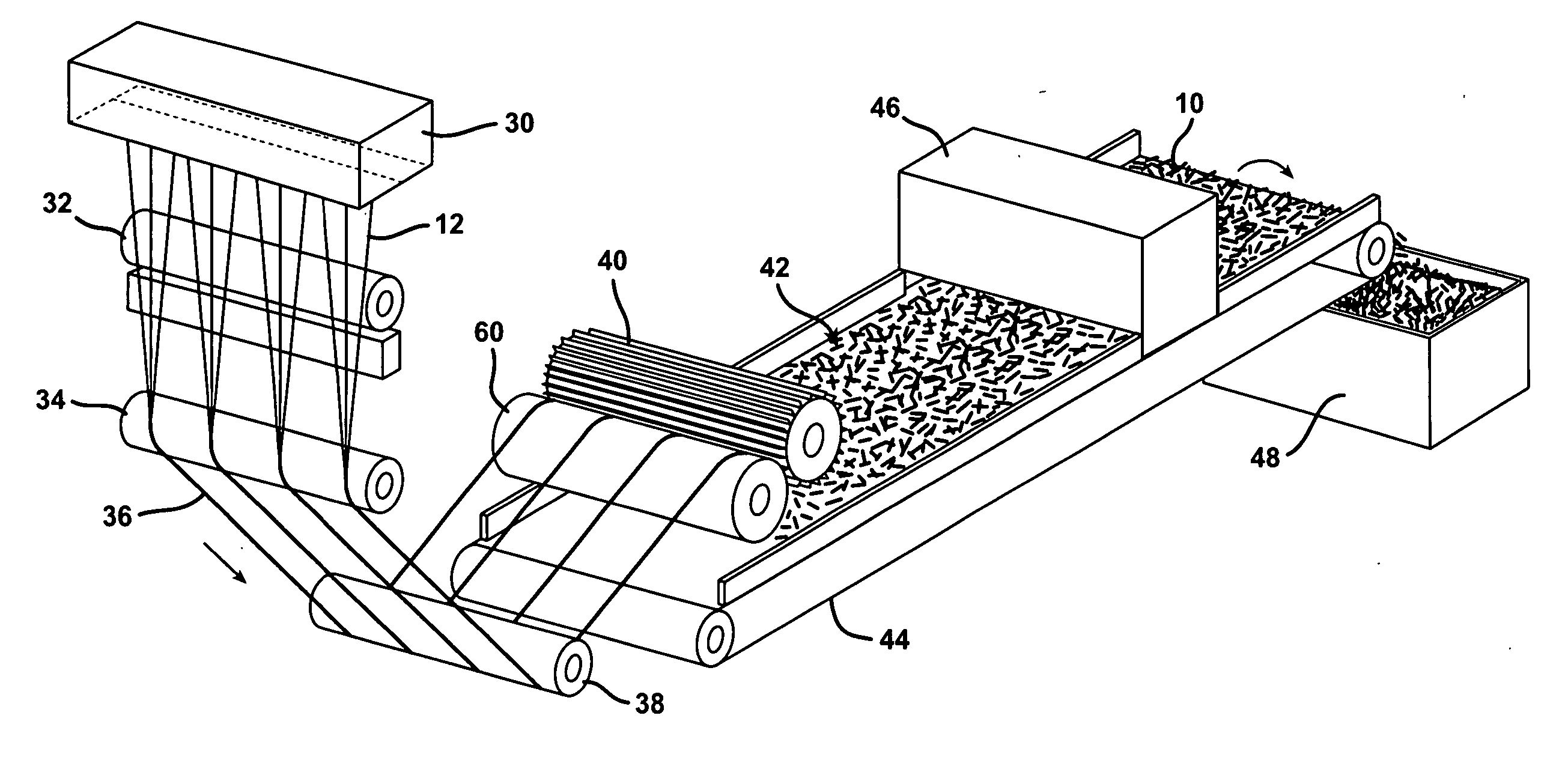
[0077] Each of the sizes set forth in Tables 1-4 were prepared and applied in a conventional manner to E-glass attenuated to 13 μm glass filaments in a 75 lb / hr throughput bushing fitted with 2052 hole tip plate. The sized fibers were split 16 ways to achieve 128 filaments per glass fiber bundle and passed through a heat transfer chamber where air heated by the extreme heat generated by the bushing was drawn into the heat transfer chamber to dry the glass fiber bundles. The dried glass fiber bundles had a bundle tex of about 43 g / km. The dried glass fiber bundles were gathered into one tow and chopped with a mechanical cot-cutter combination to a length of 1 ¼ inches. The chopped glass fibers were gathered into a plastic pan. The glass fibers contained 0% forming moisture.

example 3

Formation of Bulk Molding Compound Utilizing Various Sizing Compositions

[0078] One quarter inch (¼″) chopped glass fiber samples were made into bulk molding compounds with the formulation set forth in Table 5.

TABLE 5Bulk Molding Compound FormulationpphComponent(Parts Per Hundred)Polyester Resin E-342(a)60Thermoplastic P-713(b)40tBPB(c)1.5Calwhite II(d)200Zinc Stearate(e)4

(a)unsaturated polyester resin (AOC)

(b)thermoplastic (AOC)

(c)tert-butylperbenzoate catalyst

(d)calcium carbonate (Cabot)

(e)mold release agent (Aldrich Chemical Co.)

[0079] The bulk molding compound formulation in Table 5 was prepared with various experimental glasses sized with the various sizing compositions at 20% by weight. The various experimental glass fibers are set forth below as Samples 1-10. The charge was placed into a 12 inch×18 inch tool and was molded at 10,000 psi at 265° F. for 5 minutes. The laminates were tested for resistance to notched impact strength according to ASTM D256 in the 0° and 90°...


PUM

PropertyMeasurementUnit
Percent by massaaaaaaaaaa

Abstract

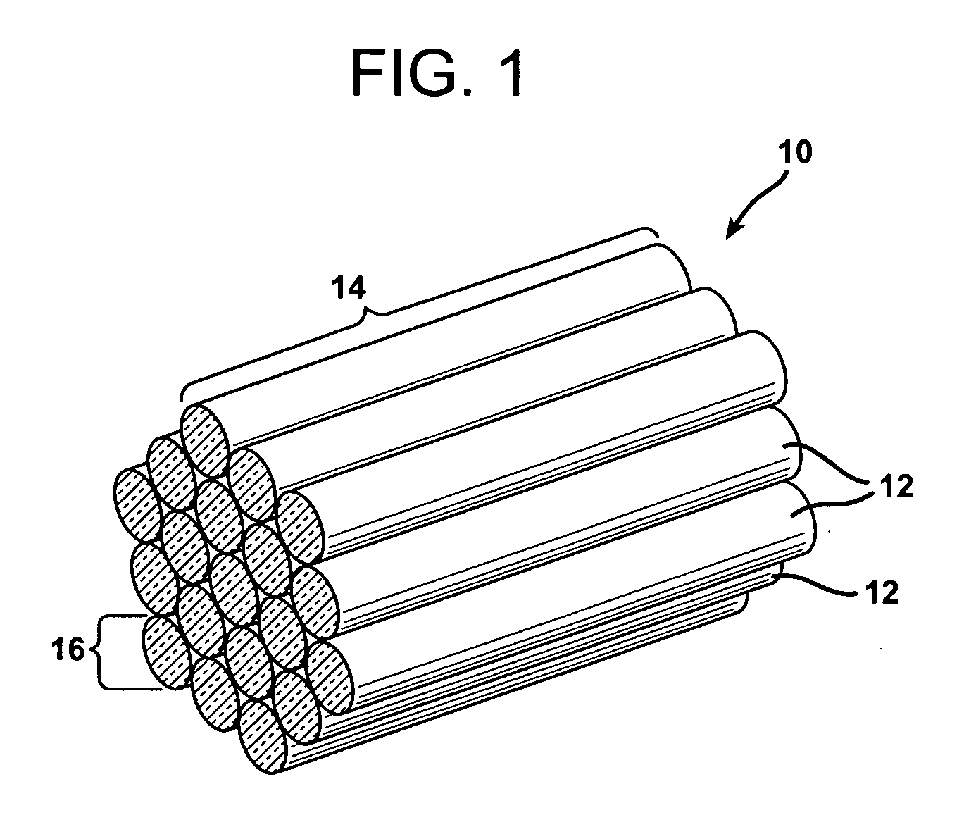
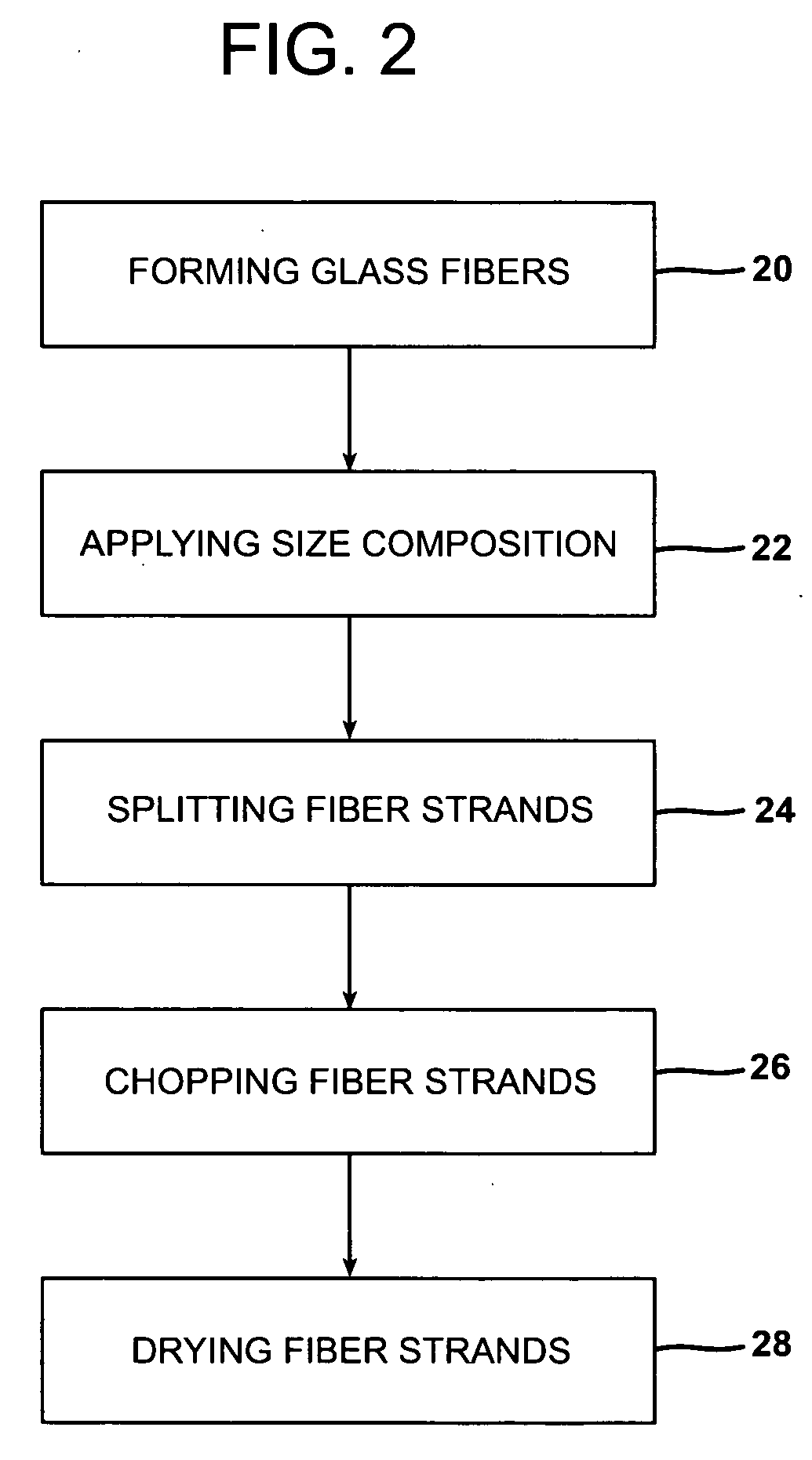
Dried bundles of chopped glass fibers that may be used in compression and injection molding applications is provided. The chopped glass fiber bundles are formed of individual glass fibers positioned in a substantial parallel orientation. The dried chopped glass fiber bundles may be prepared by applying a size composition to attenuated glass fibers, splitting the fibers to obtain a desired bundle tex, chopping the wet glass bundles to a discrete length, and drying the wet glass bundles in a dielectric oven. Alternatively, the dried chopped glass bundles may be prepared by sizing attenuated glass fibers, passing the sized fibers through a heat transfer chamber where air heated by a bushing is drawn into the heat transfer chamber to dry the glass fiber bundles, splitting the dried, sized glass fiber bundles to obtain a desired bundle tex, and chopping the dried bundles of glass fibers.

Description

CROSS REFERENCE TO RELATED APPLICATIONS [0001] This application is a continuation-in-part of U.S. patent application Ser. No. 11 / 224,246 entitled “Glass Fiber Bundles For Mat Applications And Methods of Making The Same” filed Sep. 12, 2005, the content of which is incorporated by reference in its entirety.TECHNICAL FIELD AND INDUSTRIAL APPLICABILITY OF THE INVENTION [0002] The present invention relates generally to reinforced thermoplastic and thermoset composites, and more particularly, to dried bundles of chopped glass fibers that may be used as a replacement for glass forms conventionally utilized in compression or injection molding applications to form reinforced composites. BACKGROUND OF THE INVENTION [0003] Typically, glass fibers are formed by drawing molten glass into filaments through a bushing or orifice plate and applying an aqueous sizing composition containing lubricants, coupling agents, and film-forming binder resins to the filaments. The sizing composition provides p...

Claims


Application Information

Patent Timeline
IPC IPC(8): B29C45/00
CPCB29C43/02F26B17/04B29C45/0005B29C70/12B29C70/14B29C70/46B29K2105/0809B29K2309/08C03C25/26C03C25/323C03C25/326C03C25/36F26B3/347F26B13/001B29C43/34
Inventor HAGER, WILLIAM G.SHIPP, DAVID L.ADZLMA, LEONARD J.GALLOWAY, EUGENE V.GRUBE, FRED C.MERCER, DAVID T.
Owner OCV INTELLECTUAL CAPITAL LLC
Learn More