
Perpendicular magnetic recording medium, manufacturing method therefor, and magnetic read/write apparatus using the same

a manufacturing method and magnetic recording technology, applied in the field of perpendicular magnetic recording medium, manufacturing method therefor, and magnetic read/write apparatus using the same, can solve the problems of medium noise, deterioration of read/write performance, and small volume per bit of magnetic film, etc., to achieve excellent snr performance, improve snr, and high density recording

Inactive Publication Date: 2007-03-22
KK TOSHIBA +1
View PDF11 Cites 14 Cited by
  • Summary
  • Abstract
  • Description
  • Claims
  • Application Information

AI Technical Summary

Benefits of technology

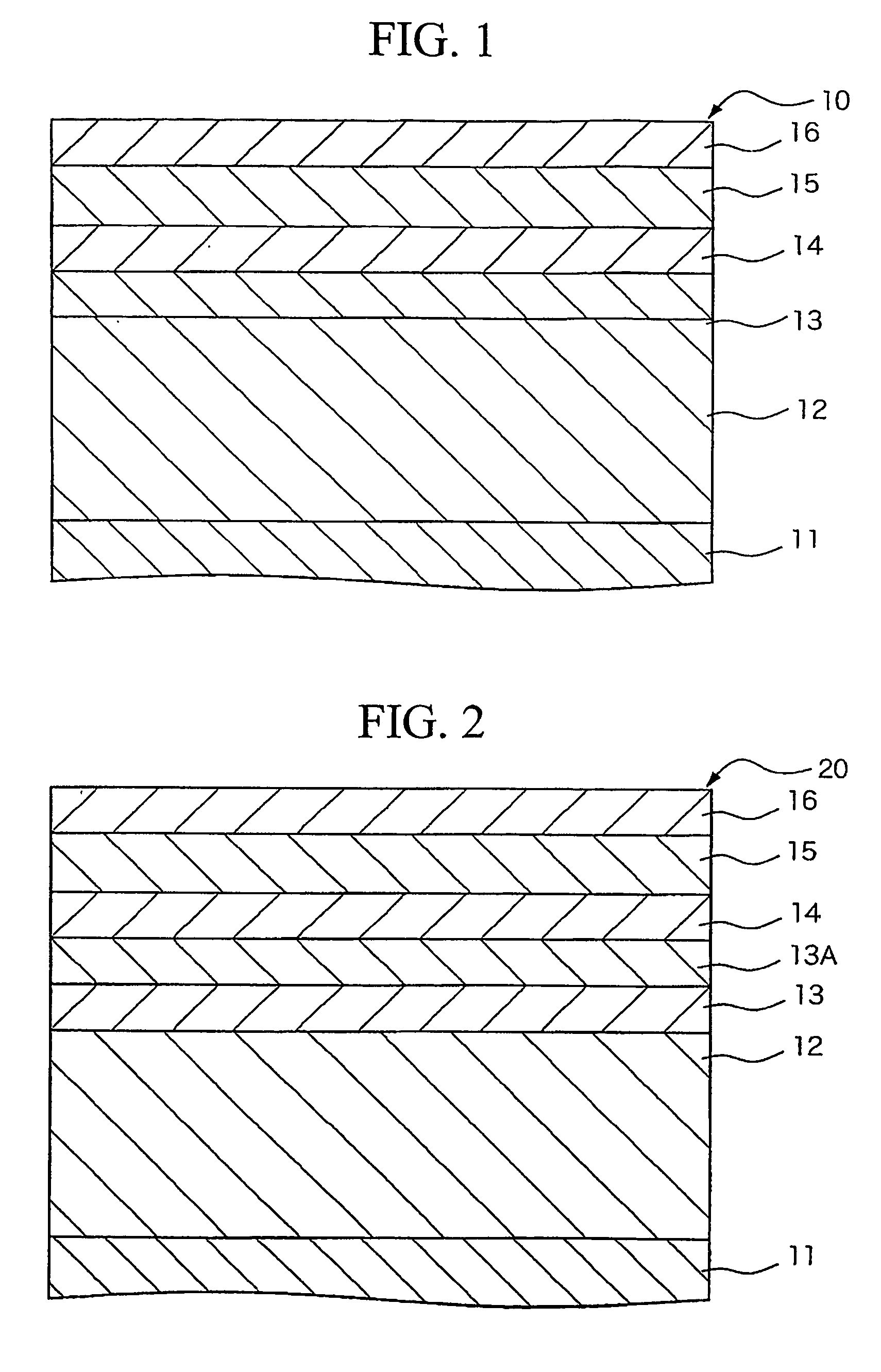
[0103] In addition to the same advantageous effects as the perpendicular magnetic recording medium of the first embodiment, the perpendicular magnetic recording medium 20 in this embodiment exhibits a better SNR since the underlayer is made of three layers.
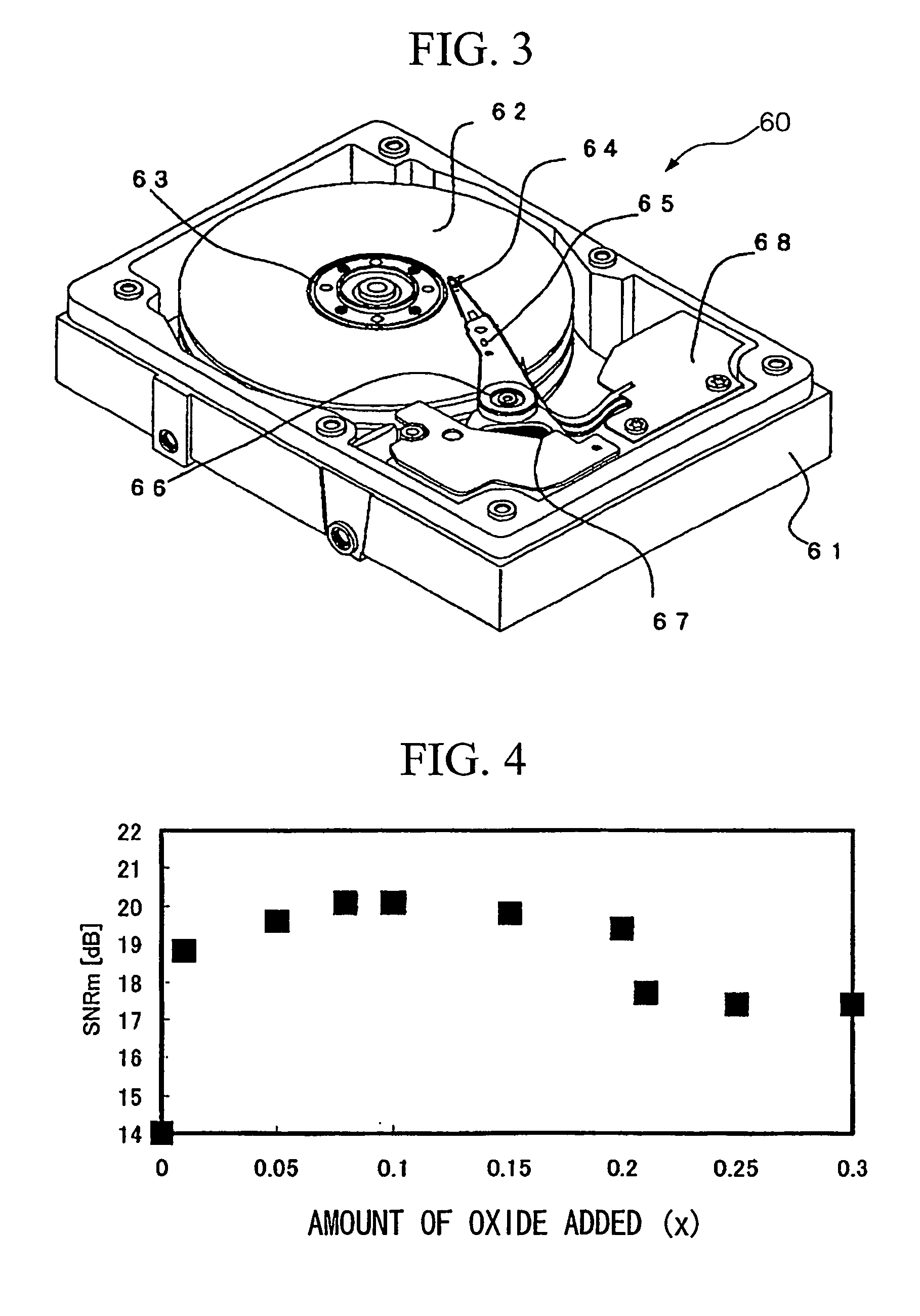
[0104]FIG. 3 is a partially exploded view of one example of a magnetic recording apparatus according to the present invention.
[0105] As shown in FIG. 3, a perpendicular magnetic recording apparatus of the present invention includes a box-shaped housing 61 with top thereof open, and a top cover (not shown) which is fixed to the housing with a plurality of screws so that the top opening of the housing is closed.
[0106] Within the housing 61, are disposed a magnetic storage medium 62 employing the perpendicular magnetic recording medium 10 described above, a spindle motor 63 as driving means to support and rotate the magnetic storage medium 62, a magnetic head 64 which writes or reads magnetic signals on the magnetic storage medium 62, a head actuator 65 which has a suspension having the magnetic head 64 at one end and movably supports the magnetic head 64 with respect to the magnetic storage medium 62, a rotary shaft 66 which rotatably supports the head actuator 65, a voice coil motor 67 which rotates and positions the actuator 65 via the rotary shaft 66, and a head amplifier circuit 68.
[0107] As shown in this example, the perpendicular magnetic recording medium 10 according to various embodiments of the present invention may be used in the magnetic storage medium 62 of the perpendicular magnetic recording apparatus 60.
[0108] As described above, according to the perpendicular magnetic read / write apparatus of this embodiment, a magnetic read / write apparatus which enables high density recording can be obtained by using the perpendicular magnetic recording medium 10 which has magnetic crystal particles with smaller diameter and exhibits an excellent SNR performance without having the deteriorated crystallinity and orientation of the magnetic crystal particles.

Problems solved by technology

In an in-plane magnetic recording medium, when the recording density is increased, the volume per bit of the magnetic film becomes too small, and thus there is the possibility that the read / write performances will deteriorate due to thermal fluctuation effects.
In addition, when the recording density is increased, there is a tendency for the medium noise to increase due to the influence of the demagnetizing field at the boundary area between recording bits.
However, since the size of the magnetic particles has yet to be satisfactorily achieved by segregation of Cr and magnetic crystal particles not being sufficiently separated spatially, magnetic interaction between particles cannot be satisfactory reduced.
This, in turn, causes another problem of being unable to sufficiently reduce transition noise between recording bits.
However, since the diffusion rate of SiOx in a film is low, a sufficient amount of SiOx cannot be segregated at the boundaries of the magnetic crystal particles.
As a result, a part of SiOx which has not been precipitated may form a super-saturated solid solution with the magnetic crystal particles, which lowers the crystallinity and orientation of the magnetic crystal particles, resulting in a decreased signal-noise ratio (SNR) of the reading / writing (R / W) performance.

Method used


Image

  • Perpendicular magnetic recording medium, manufacturing method therefor, and magnetic read/write apparatus using the same
  • Perpendicular magnetic recording medium, manufacturing method therefor, and magnetic read/write apparatus using the same
  • Perpendicular magnetic recording medium, manufacturing method therefor, and magnetic read/write apparatus using the same

Examples


example 1

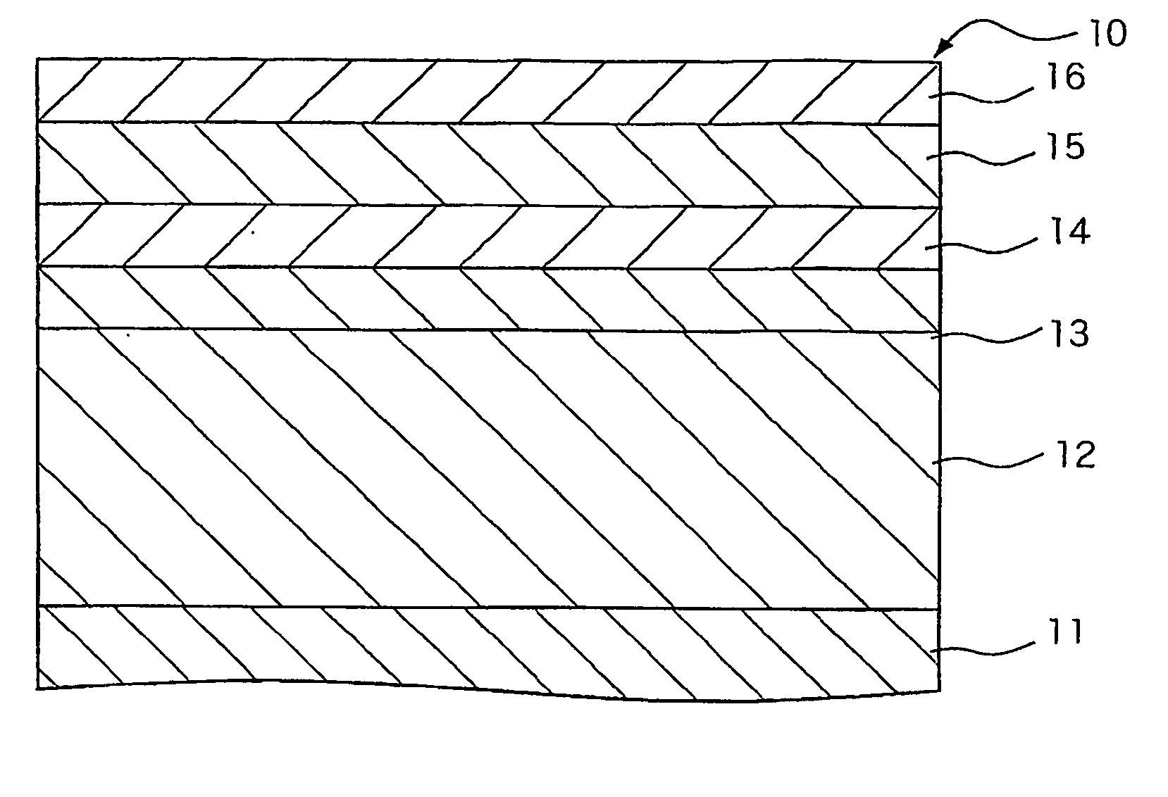
[0110] For Example 1, a perpendicular magnetic recording medium having a structure shown in FIG. 1 was fabricated. First, a non-magnetic glass substrate which has a diameter of 2.5 inches in the shape of a hard disk was provided.

[0111] After evacuating a chamber for sputtering equipment from atmospheric pressure to a pressure of 2×10⁻⁵ Pa or lower, a Co84Zr6Nb10 soft magnetic layer having a thickness of 200 nm was deposited as a soft magnetic layer using a Co84Zr6Nb10 target, and then a Ta layer having a thickness of 8 nm was deposited as a second underlayer using a Ta target under an argon atmosphere of 0.67 Pa. Then, a Ru layer was deposited to a thickness of 15 nm as a first underlayer using a Ru target under an argon atmosphere of 3 Pa.

[0112] Next, a magnetic recording layer having a thickness of 15 nm was formed using a composite target (Co —10 at % Cr —14 at % Pt, SiO2, and Li2O) as a material of magnetic crystal particle material. Carbon was deposited to a thickness of 7 μm...

example 2

[0128] For Example 2, a non-magnetic glass substrate in the shape of a 2.5-inch hard disk was provided.

[0129] After evacuating a chamber for sputtering equipment from atmospheric pressure to a pressure of 2×10⁻⁵ Pa or lower, a Co84Zr6Nb10 soft magnetic layer having a thickness of 200 nm was deposited as a soft magnetic layer using a Co84Zr6Nb10 target, and then a Ta layer having a thickness of 8 nm was deposited as a second underlayer using a Ta target under an argon atmosphere of 0.67 Pa. Then, a Ru layer was deposited to a thickness of 15 nm as a first underlayer using a Ru target under an argon atmosphere of 3 Pa.

[0130] Next, a magnetic recording layer having a thickness of 15 nm was formed using a composite target (Co —10 at % Cr —14 at % Pt, SiO2, and Li2O) as a material of magnetic crystal particle material. Carbon was deposited to a thickness of 7 nm as a protective layer under an argon atmosphere of 0.67 Pa. After forming the layers, perfluoro polyether (PFPE) lubricant wa...

example 3

[0142] For Example 3, a non-magnetic glass substrate in the shape of a 2.5-inch hard disk was provided.

[0143] After evacuating a chamber for sputtering equipment from atmospheric pressure to a pressure of 2×10⁻⁵ Pa or lower, a Co84Zr6Nb10 soft magnetic layer having a thickness of 200 nm was deposited as a soft magnetic layer using a Co84Zr6Nb10 target, and then a Ta layer having a thickness of 8 nm was deposited as a second underlayer using a Ta target under an argon atmosphere of 0.67 Pa. Then, a Ru—SiO2—Li2O layer was deposited to a thickness of 15 nm as a first underlayer using a composite target including Ru, SiO2, and Li2O under an argon atmosphere of 3 Pa.

[0144] Next, a magnetic recording layer having a thickness of 15 nm was formed using a composite target which contains Co—10 at % Cr—14 at % Pt, SiO2, and Li2O as magnetic crystal particle materials. Carbon was deposited to a thickness of 7 nm as a protective layer under an argon atmosphere of 0.67 Pa. After forming the lay...


PUM


Abstract

A perpendicular magnetic recording medium includes: a substrate; at least one underlayer formed above the substrate; and a perpendicular magnetic recording layer formed above the at least one underlayer, an easy magnetization axis of the perpendicular magnetic recording layer being oriented perpendicular to the substrate, the perpendicular magnetic recording layer including magnetic crystal particles and grain boundaries surrounding the magnetic crystal particles, wherein the grain boundaries contain an oxide of silicon and at least one element selected from the group consisting of Li, Na, K, Rb, Cs, Ca, Sr, and Ba, and the ratio of a total amount of substance of Si, Li, Na, K, Rb, Cs, Ca, Sr, and Ba in the perpendicular magnetic recording layer is no less than 1 mol % and no more than 20 mol %.

Description

[0001] This application claims the benefit of Japanese Patent Application No. 2003-347192 filed Oct. 6, 2003, and U.S. Provisional Application No. 60 / 503,996 filed Oct. 10, 2003, the contents of which are incorporated herein by reference.TECHNICAL FIELD [0002] The present invention relates to a particle dispersion type magnetic storage medium used in hard disk drives, to a manufacturing method therefor, and to a technology which is suitably used in a magnetic read / write apparatus. BACKGROUND ART [0003] Magnetic storage devices (HDDs) which is capable of reading and writing information have been commonly used in computers. Recently, advantages of such hard disk drives, including large storage capacity, a relatively low prices, fast data access, and high reliability of data retention, have broadened their application to various areas, such as household VCRs, audio appliances, or vehicle-mounted navigation systems. As the application of hard disk drives diversified, a demand for increa...

Claims


Application Information

Patent Timeline
IPC IPC(8): G11B5/82H01L21/00G11B5/65G11B5/64G11B5/73G11B5/738G11B5/84H01F10/16H01F41/20
CPCG11B5/65G11B5/7325G11B5/656G11B5/7368G11B5/7377G11B5/658
Inventor MAEDA, TOMOYUKIOKAWA, SOICHIIWASAKI, TAKESHINAKAMURA, FUTOSHISAKAI, HIROSHISHIMIZU, KENJISAKAWAKI, AKIRA
Owner KK TOSHIBA
Learn More