Variable engine valve control system with pressure difference

a valve control system and variable engine technology, applied in the direction of valve drives, machines/engines, non-mechanical valves, etc., can solve the problems of not meeting the requirements of high/low speed simultaneously, improving control, and unsatisfactory engine performance, so as to increase the response speed and increase the response speed of the system , the effect of increasing the operating speed of the combustion engin

Inactive Publication Date: 2007-04-12
NINGBO HOYEA MACHINERY MFG
View PDF2 Cites 10 Cited by
  • Summary
  • Abstract
  • Description
  • Claims
  • Application Information

AI Technical Summary

Benefits of technology

[0013] As compared to the present technology, this invention has advantageous in: since utilizing pressure difference proportional relief valve as key control element, the height of the valve opening is not related to the pressure of the system, which is only depended on the pressure difference between the upper and the lower chambers of the hydraulic cylinder, therefore it does not need to use the displacement transducer to perform closed loop control, it only needs to change electric signal to change the pressure difference of the upper and lower chambers of the hydraulic cylinder thereby attain the object of making variable valve lift and timing at any time as required, therefore the pressure difference proportional relief valve can be used instead of the change valve so as to make the system response speed fast, control simple, cost low, reliability fine. With short operating fluid passage the system is less interfered because the operating mode of the pressure difference proportional relief valve is normally opened without dead area, which can be directly mounted at the side of the cylinder. Furthermore, a hydraulic control check valve situated between the upper and lower chambers of the hydraulic cylinder causes the return stroke of the piston faster to increase its response speed. The control spring is fitted outside of the hydraulic cylinder to make the performance of the spring no longer restricted by the volume of the hydraulic cylinder, which is more helpful for increasing the response speed of the system. Therefore, this invention can meet the requirement of higher operating speed of combustion engines. It can be popularized and applied on combustion engines.

Problems solved by technology

When operating, valve timing (sequential control) and valve lift cannot change at any time according to working demand and therefore it cannot meet the requirements of high / low speed simultaneously.
With the valve apparatus described above, variable timing and variable lift still cannot be independently controlled, the performance of the engine is still not ideal though it can economize fuel consumption, decrease waste gas displacement and obviously improve the performance of the engine.
In laboratory experiment, it can economize fuel high up to 18% and decrease production of hydrocarbon, but in operating process it is found when the armature approaching the stop iron, the magnetic force rises very fast and it is difficult to improve controlling collision, consequently, its control reliability and firmness are worse and it cannot provide variable lift.
Additionally, for increasing actuating force, it is necessary to add an additional battery besides the original battery of 12 V, but there are no more places for installing much more extra batteries in the present narrow space.
Therefore, this kind of structure restricts extensive use of the electromechanical type variable valve control system.
However, the patent described above has not been applied yet, it is analyzed after researched: (1) Along with the development of technology, the speed of automobile engines are more and more faster, completing four operating processes only needs 0.005 seconds, so, the response time of the change valve requires very fast.
In order to meet the requirement of such a short response time, the cost of making change valve will be very high and finally leading to the products very expensive thereof no industrialized production can be carried out; (2) Because of the hydraulic cylinder embracing a control piston, a control chamber and control spring, the electrichydraulic pressure regulator, etc are positioned in the hydraulic circuit to make its system relative complicated and its reliability poor; (3) The opening height of the valve is related to the pressure of the hydraulic system, therefore, it is subjected to more interference from the system with shortcomings of large pulsation, etc.

Method used


Image

  • Variable engine valve control system with pressure difference
  • Variable engine valve control system with pressure difference
  • Variable engine valve control system with pressure difference

Examples


Embodiment Construction

[0020] Further description in detail will be made in the following embodiments with the drawings for this invention.

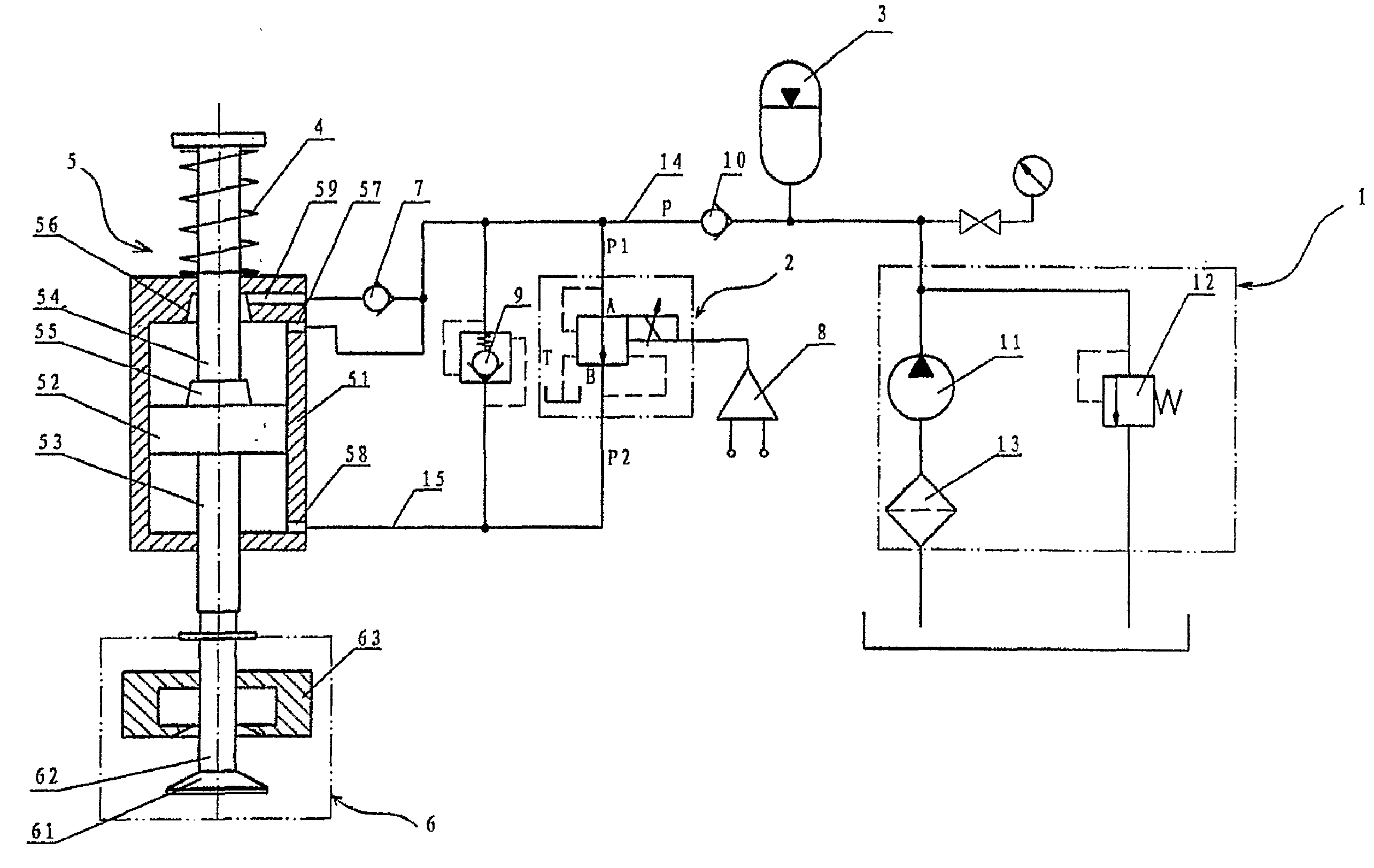
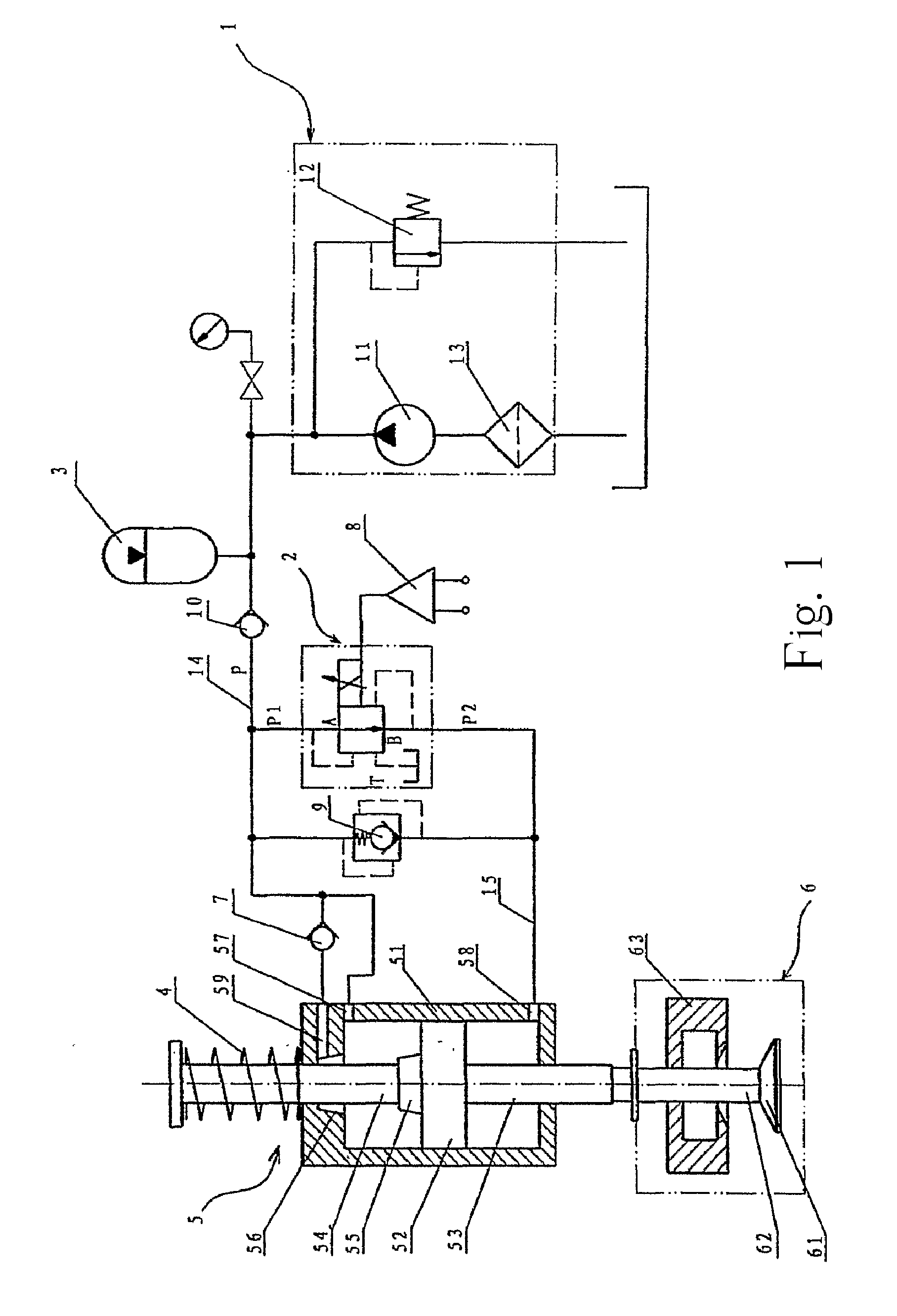
[0021] Embodiment 1: as shown in FIG. 1 the variable engine valve control system with pressure difference consists of hydraulic supply equipment 1, hydraulic actuator apparatus 5, valve 6 and spring 4 controlling the piston balance. The said hydraulic actuator apparatus 5 contains hydraulic cylinder 51, piston 52, piston rod 53. The valve 6 comprises valve head 61, valve stem 62 and valve seat 63. The hydraulic supply equipment 1 includes hydraulic pump 11 and pressure regulating valve 12. Mechanical connection can be carried out according to conventional technology between piston rod 53 and valve stem 62 or force transmission carried out by means of free floating to realize linkage of piston rod 53 and valve head 61; piston 52 divides hydraulic cylinder 51 into upper chamber and lower chamber, the upper chamber of hydraulic cylinder 51 is connected with the fluid out...


PUM


Abstract

A kind of variable engine valve control system with pressure difference comprises hydraulic supply equipment, hydraulic actuator apparatus, valve and spring controlling piston balance. The hydraulic actuator comprises hydraulic cylinder, piston and piston rod. The piston rod is coupled and moved with the valve. It is characterized by that the said piston divides the hydraulic cylinder into upper chamber and lower chamber. The said hydraulic supply equipment is connected with the upper chamber of the hydraulic cylinder through the fluid inlet pipe and the said lower chamber of the hydraulic cylinder is connected with the hydraulic supply equipment through the pressure difference proportional relief valve. Utilizing pressure difference proportional relief valve as key control element, the height of the valve opening is not related to the pressure of the system, it only needs to change electric signal to vary the pressure difference of the upper and lower chambers of the piston thereby attain the object of making variable valve lift and timing at any time as required. Therefore, the system has fast response speed, simple structure, low cost, fine reliability, and less interference. Consequently, this invention can meet the requirement of higher operating speed of internal combustion engines. It can be popularized and applied in internal combustion engines.

Description

FIELD OF THE INVENTION [0001] This invention involves a kind of internal combustion engine valve control system, particularly a kind of variable internal combustion engine valve control system with electric hydraulic control. BACKGROUND OF THE INVENTION [0002] The engine valve apparatus is an assembly of the engine valve mechanism. Since the operation of the internal combustion engine comprises four working processes of air intake, compression, doing work, exhaust, wherein the air intake and exhaust processes need to depend on the engine valve mechanism to convey combustible mixture exactly according to the working sequence of each cylinder (gasoline engine) or fresh air (diesel engine) and exhaust waste gas after burnt, the work described above is done by the valve of the valve mechanism thereby the valve apparatus plays a very important role in the operation of the engine, whereas the conventional valve mechanism is composed of cam shaft, valve rocker, valve spring, valve guide pi...

Claims


Application Information

Patent Timeline
Patent Type & Authority Applications(United States)
IPC IPC(8): F01L9/02F01L1/34F01L9/10F01L1/02F01L9/40F01L13/00F02D13/00
CPCF01L9/02F01L2001/34446F01L9/10
Inventor LING, JUNJIEWENG, ZHENTAO
Owner NINGBO HOYEA MACHINERY MFG
Why Eureka
Try Eureka