Balloon catheter system for treating vascular occlusions

a balloon catheter and vascular occlusion technology, applied in balloon catheters, stents, dilators, etc., can solve the problems of higher equipment costs, lower success rates, and higher restraint rates

Inactive Publication Date: 2007-04-19
ENDOCROSS
View PDF0 Cites 141 Cited by
  • Summary
  • Abstract
  • Description
  • Claims
  • Application Information

AI Technical Summary

Benefits of technology

[0069] said middle portion inner conduit is capable of responding to further expansion of the balloon from said second expanded state to a third expanded state by increasi

Problems solved by technology

However, PCI of cases of CTO have historically posed problems, with lower success rates (40 to 80 percent-average 60 percent), higher equipment costs, and a higher restenosis rate.
Conventional intervention tools such as angioplasty balloons are often too flexible or blunt to cross the CTO site, which often contains extremely hard, calcified tissue that may form an impenetrable barrier to the advancement of a guidewire therethrough.
Even a less than total occlusion may contain complex structures which may trap or divert the steering end of the guidewire.
In view of the great difficulties encountered in attempting to properly position a guidewire across the stenosis, conventional guided atherectomy or dilatation devices such as cutting elements and balloons cannot be used

Method used


Image

  • Balloon catheter system for treating vascular occlusions
  • Balloon catheter system for treating vascular occlusions
  • Balloon catheter system for treating vascular occlusions

Examples


first main embodiment

ng Oscillating Catheter Shaft Distal Tip

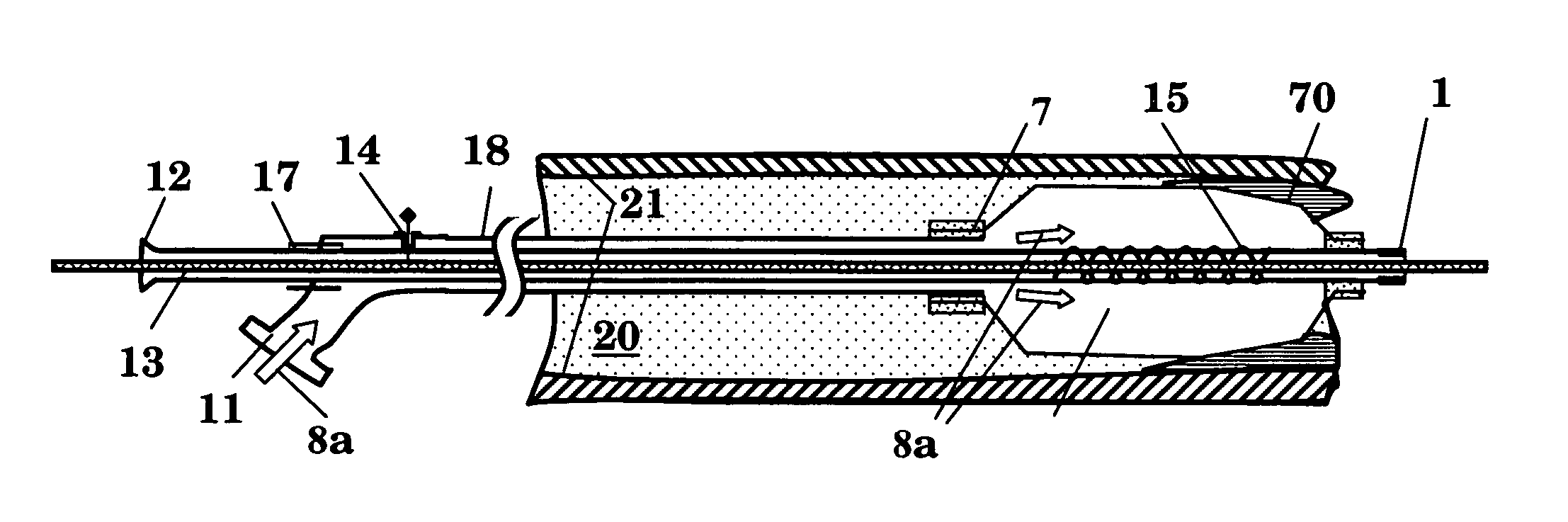
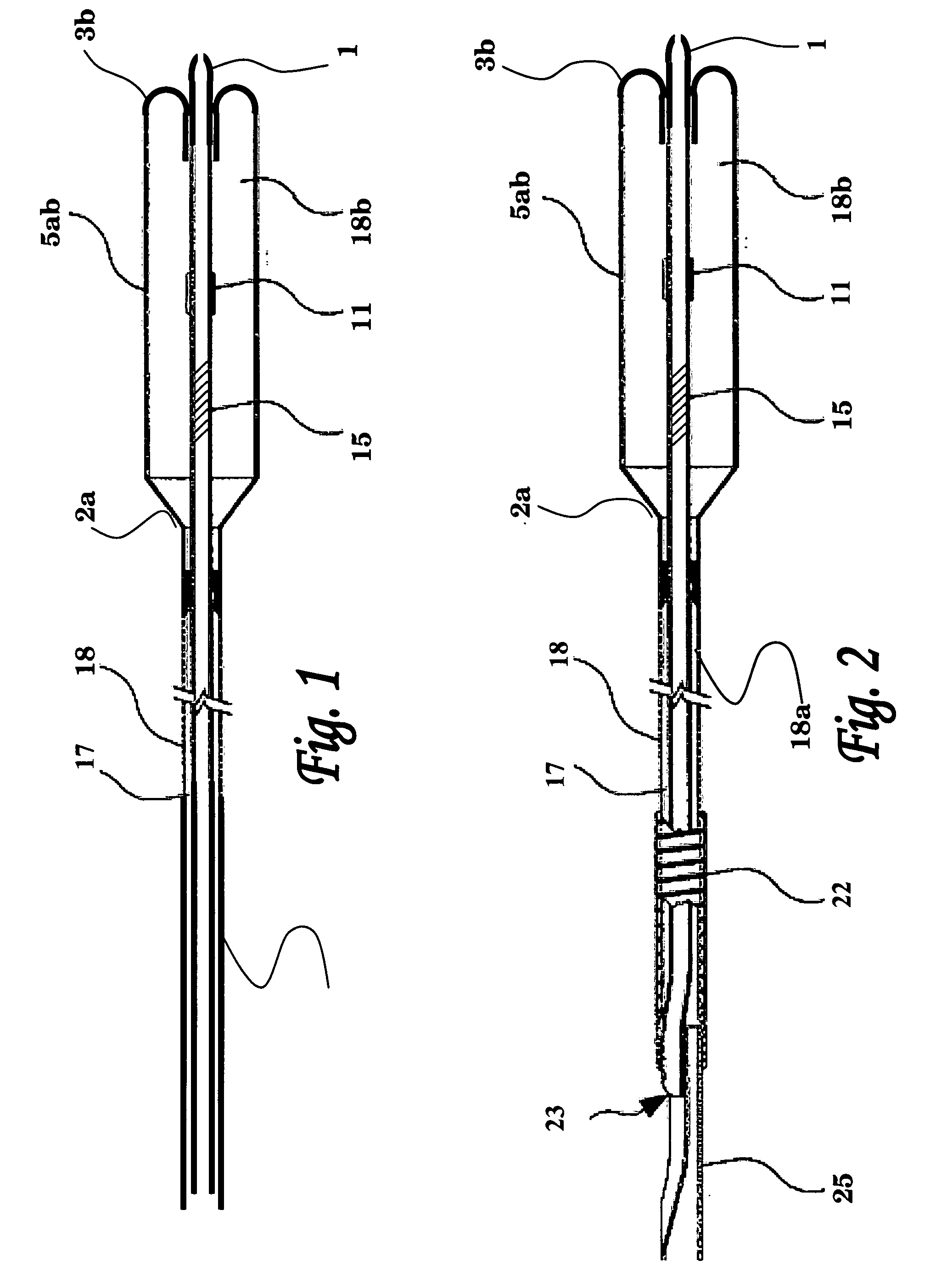
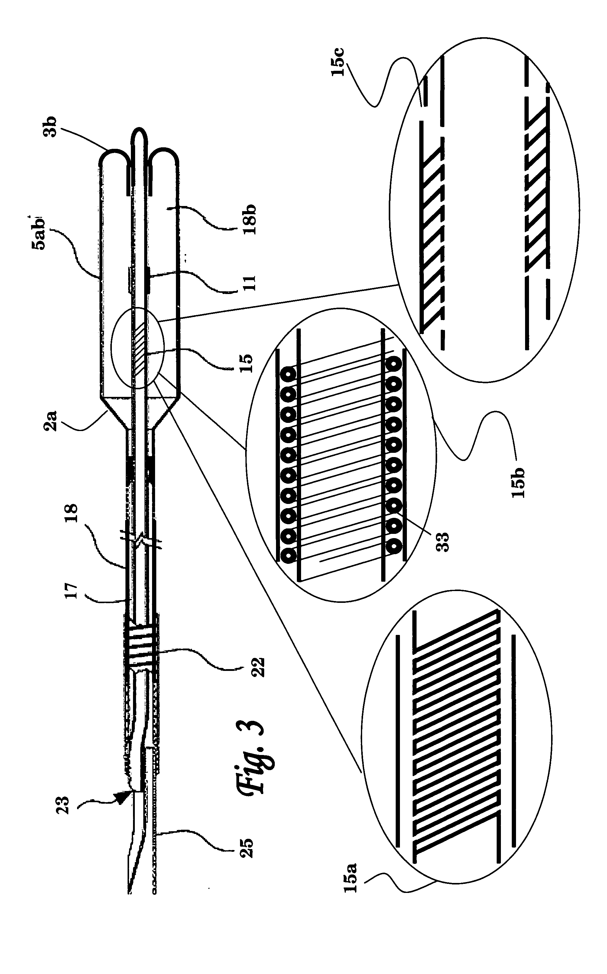
[0108]FIG. 1 schematically illustrates an over the wire implementation of the balloon catheter of the invention. This balloon catheter implementation comprises an outer shaft 18, inner shaft 17 passing thereinside, and a balloon 5ab. The lumen of inner shaft 17 may be used for passing a guide wire thereinside, which may be introduced via its proximal opening (e.g., 12 in FIGS. 7A-7F).

[0109] In the pre-charged embodiment shown in this figure, balloon 5ab has a conical proximal end 2a which tapers proximally towards its annular attachment area on the outer surface of the distal end portion of outer shaft 18, and a rounded distal end 3b which is obtained by folding the distal end of balloon 5ab proximally inwardly and by attaching the outer surface of its distal end portion to an annular attachment area on the outer surface of the distal end portion of inner shaft 17. Other types of balloon attachment (resulting in either pre-charged or non-char...

second main embodiment

g Oscillating Guide Wire Immobilized within Catheter Shaft

[0148] In this second main embodiment of the invention, the balloon catheter system comprises a guidewire (also referred to herein as a ramming tool) immobilized within an inner catheter shaft lumen, wherein the balloon catheter is capable of delivering rapid motion to the guidewire passing therein. The in vivo application of such rapid motion to, or adjacent to, an occlusion formed in a body organ or pathway is effectively utilized for fracturing the occluding matter and for perforating a passage thereinside, that may allow crossing and / or removing the occluding matter.

[0149] The balloon catheter of the invention is preferably constructed from concentric tubes having an inflatable member, such as a balloon, attached to their distal ends. The inflatable member can be a sleeve having tapering ends that can be sealably attached to the distal end portions of the inner and outer tubes of the catheter device, such that the lumen ...


PUM


Abstract

The present invention provides a balloon catheter comprising: a hollow inner shaft disposed within a hollow outer shaft; a balloon attached at its proximal end to said outer shaft and at its distal end to said inner shaft; wherein the inner shaft is constructed such that following radial expansion of the balloon to a first expanded state, said inner shaft is capable of responding to further longitudinal expansion of the balloon to a second expanded state by increasing its length from a resting value, and of responding to subsequent partial deflation back to said first expanded state by reducing its length back to said resting value.

Description

FIELD OF THE INVENTION [0001] The present invention relates to balloon catheter systems. More specifically, the present invention provides crossing balloon systems (CBS) for use in the treatment of chronic total occlusion (CTO) and related conditions in blood vessels. BACKGROUND OF THE INVENTION [0002] Chronic total occlusion of a blood vessel is, as the name suggests, a condition in which there is complete (or near complete) obstruction of that vessel due to the development of an intravascular lesion comprising atheromatous plaque material and / or thrombic material. Between 10 and 20 percent of patients undergoing percutaneous coronary interventions (PCI) have CTO. Successful opening of CTO lesions improves anginal status, increases exercise capacity, and reduces the need for bypass surgery. However, PCI of cases of CTO have historically posed problems, with lower success rates (40 to 80 percent-average 60 percent), higher equipment costs, and a higher restenosis rate. When MACE (Ma...

Claims


Application Information

Patent Timeline
IPC IPC(8): A61M29/00A61F2/958
CPCA61M25/0052A61M25/0054A61M25/0119A61M25/1006A61M25/104A61M2025/0183A61M2025/1065A61M2025/1068
Inventor HIRSZOWICZ, ERANLEVIT, ERANDUBI, SHAY
Owner ENDOCROSS
Why Eureka
Try Eureka