Low cost high-pressure sensor

a high-pressure sensor, low-cost technology, applied in the direction of fluid pressure measurement, variable capacitors, instruments, etc., can solve the problems of inconvenient mass production of sensors, high manufacturing cost of these sensors, and inability to meet the needs of mass production

Inactive Publication Date: 2007-05-03
HONEYWELL INT INC
View PDF7 Cites 77 Cited by
  • Summary
  • Abstract
  • Description
  • Claims
  • Application Information

AI Technical Summary

Benefits of technology

[0048] The pressure sensing apparatus 1 of the present invention provides several advantages over the prior art. The inventive apparatus can be produced at a lower cost due to the requiring of less material, the use of less expensive materials, less reject cost, and less expensive fabrication cost due to a simpler fabrication process. Furthermore, multiple sensors can be fabricated on a single substrate, significantly reducing labor costs and processing time. The inventive pressure sensing apparatus further exhibits greater adhesion, greater thermal stability, and higher reliability due to a match of thermal expansion between the diaphragm assembly 13 and the disc 19.

Problems solved by technology

However, silicon is susceptible to chemical attack and erosion, particularly in environments such as where a high-pressure medium is to be sensed, such as automotive applications that involve sensing pressures of brake fluid, oil, coolant, transmission fluid, hydraulic fluid, fuel, or steering fluid, at pressures of two atmospheres or more.
Unfortunately, the manufacturing processes for these sensors are expensive and complex.
As a result, these sensors are unsuitable for mass production.
However, the circuits required to detect such capacitance changes are often complex and subject to noise corruption.
Furthermore, attaining an adequate seal between the ceramic diaphragm and the base for high pressure applications is often difficult.
However, while the signal detection circuitry may be less complicated, it is difficult to reliably seal the ceramic diaphragm with a base.
However, the equipment necessary to deposit the insulating and polysilicon layers is expensive, and deposition rates are extremely slow.
While several high temperature resistant specialty metals are known in the art, they are very expensive and difficult to machine.
However, these structures are often unreliable at higher pressures.

Method used


Image

  • Low cost high-pressure sensor
  • Low cost high-pressure sensor
  • Low cost high-pressure sensor

Examples


example 1

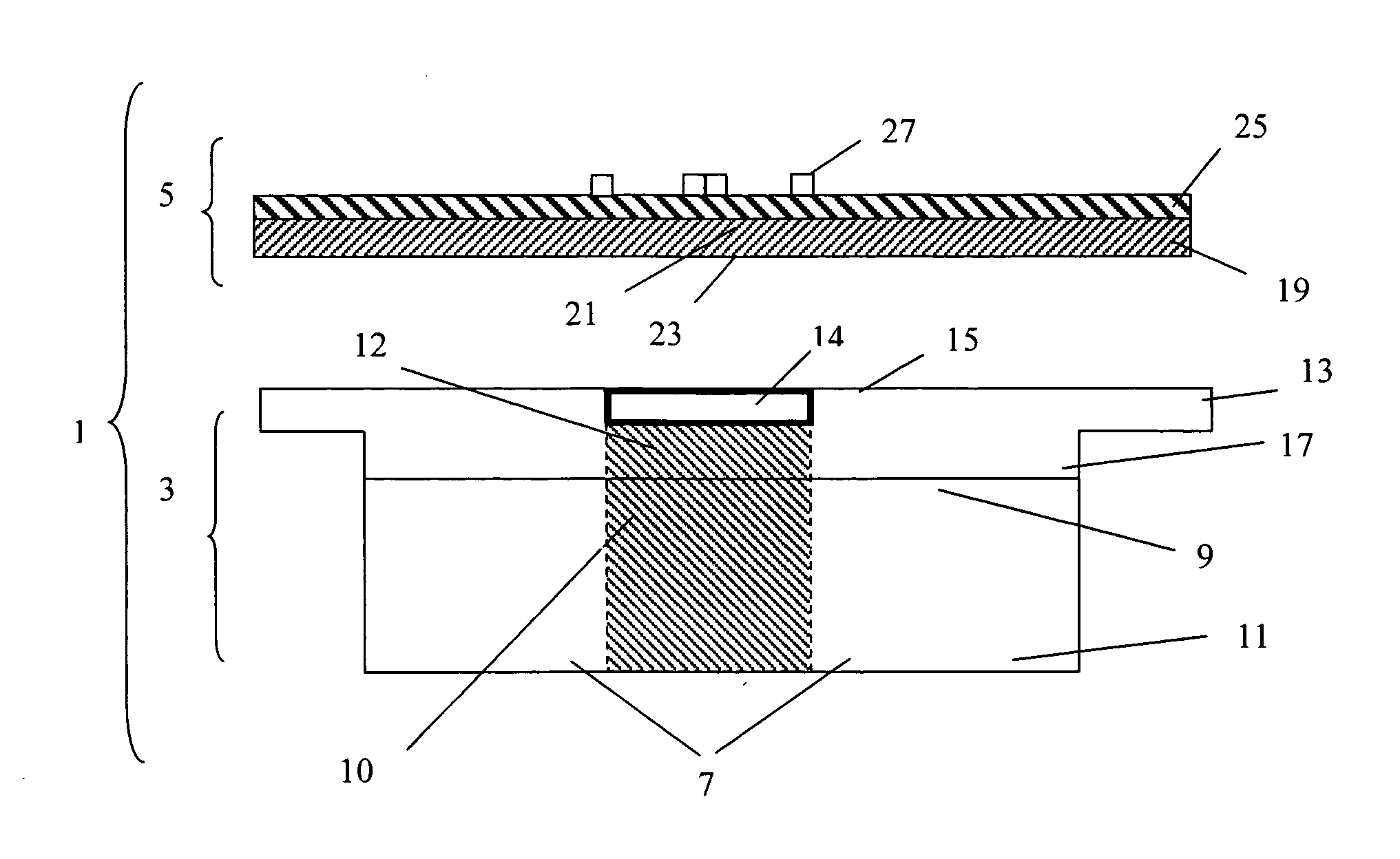
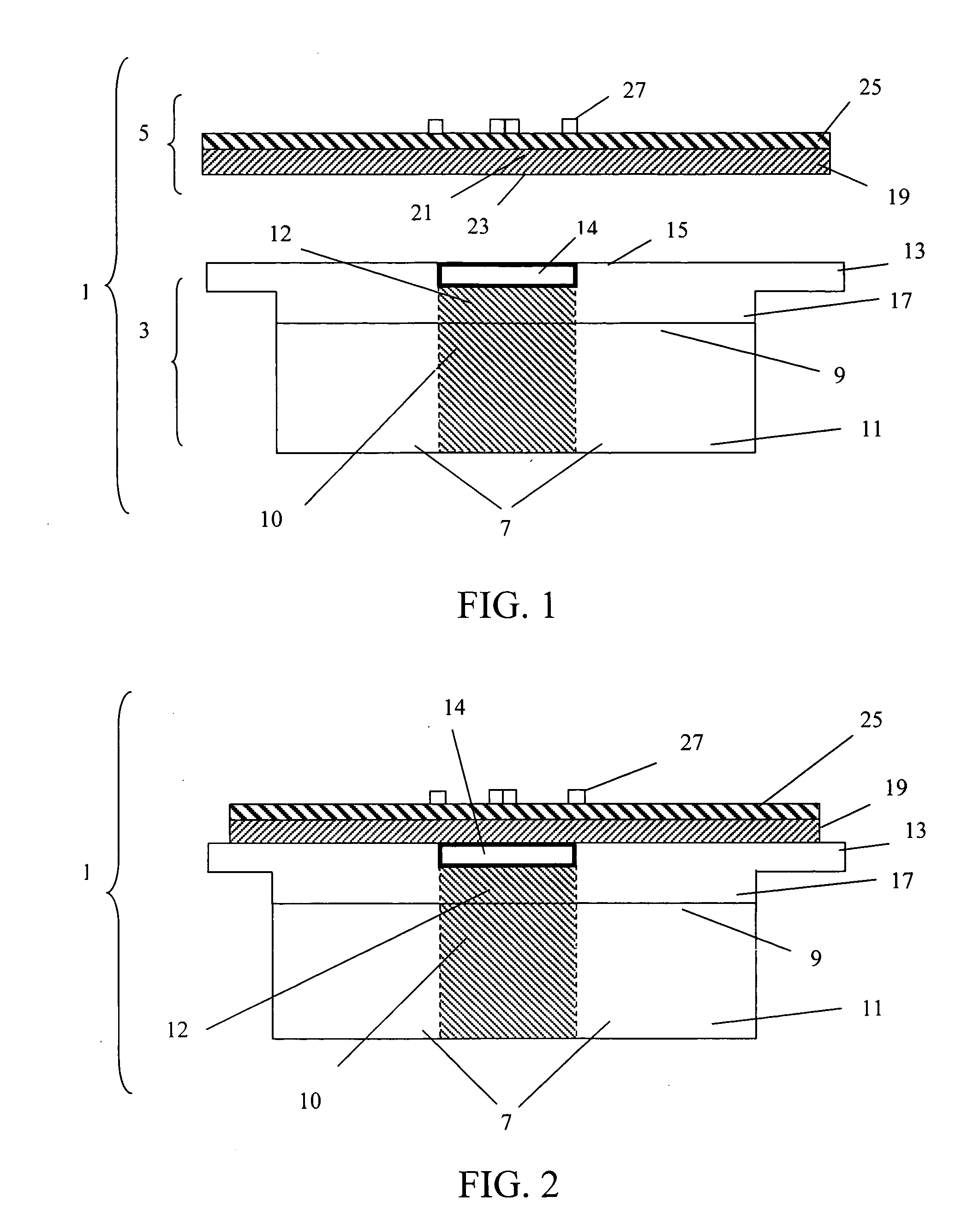
[0050] A circular, flat disc of 430 stainless steel is machined to have a diameter of 0.5 mm and a thickness of 0.1 mm, and is washed in detergent. A ceramic dielectric paste comprising alumina is screen printed onto an upper surface of the disc. The ceramic paste is dried on the disc in an oven for 10-15 minutes at 150C. The dried paste is then fired on the disc for 60-90 minutes at 850-950° C. to form a ceramic coating having a thickness of about 0.05 mm. Piezoresistive elements are then formed on the ceramic coating by first screen printing a conductive gold paste onto the ceramic coating. The conductive paste is then dried on the ceramic coating in an oven for 10-15 minutes at 150° C. The conductive paste is then fired on the ceramic coating for 60-90 minutes at 850° C. to form a conductive layer having a thickness of about 0.01 mm. A resistor paste is then screen printed onto the conductive layer. The resistor paste is then dried on the conductive layer in an oven for 10-15 min...

example 2

[0052] A circular, flat ceramic disc comprising alumina is formed, having a diameter of 0.5 mm and a thickness of 0.1 mm, and is washed in detergent. Piezoresistive elements are then formed on the ceramic coating by first screen printing a conductive gold paste onto the ceramic coating. The conductive paste is then dried on the ceramic coating in an oven for 10-15 minutes at 150° C. The conductive paste is then fired on the ceramic coating for 60-90 minutes at 850° C. to form a conductive layer having a thickness of about 10 microns. A resistor paste is then screen printed onto the conductive layer. The resistor paste is then dried on the conductive layer in an oven for 10-15 minutes at 150° C. The resistor paste is then fired on the conductive layer for 60-90 minutes at 850° C. to form a resistor layer having at thickness of about 0.02 mm.

[0053] Separately, a 316 stainless steel pressure port is welded to a 316 stainless steel diaphragm assembly. The diaphragm assembly includes a ...

example 3

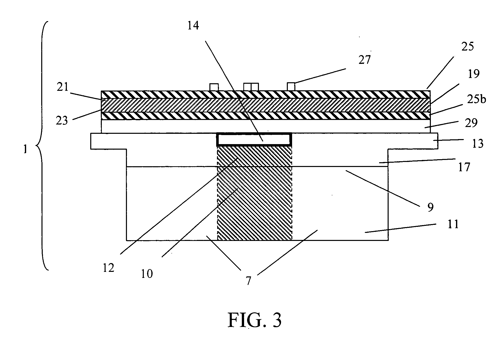
[0054] Example 1 is repeated except that after firing the resistor paste, an overglaze glass sealant paste is screen printed onto the resistor layer and dried in an oven for 10-15 minutes at 150° C. The overglaze glass sealant paste is then fired for 30-60 minutes at 500-700° C. to form an overglaze glass sealant layer having a thickness of 0.01-0.02 mm.


PUM

PropertyMeasurementUnit
thicknessaaaaaaaaaa
diameteraaaaaaaaaa
thicknessaaaaaaaaaa

Abstract

A pressure sensing apparatus including a thin disc of a metal having a ceramic material layer and piezoresistive elements formed thereon. A surface of the disc is bonded to a diaphragm assembly on a pressure port base constructed of a low cost metal. The bonding process is performed at low temperatures, (<700° C.), so that the diaphragm assembly and pressure port do not require high temperature corrosion resistance, and can thus be formed of less expensive materials. The inventive apparatus provides a lower cost alternative to conventional high pressure sensors since less material is used, less expensive materials are used, and fabrication is less complex. The inventive apparatus is also more reliable and exhibits greater thermal stability than conventional high pressure sensors.

Description

BACKGROUND OF THE INVENTION [0001] 1. Field of the Invention [0002] The invention relates to pressure sensors. In particular, it relates to high pressure sensors having increased reliability, thermal stability and adhesion properties, while being inexpensive to fabricate. [0003] 2. Description of the Related Art [0004] For years, those skilled in the art have made continuous efforts to develop pressure sensors that are low in cost and capable of being mass produced, while exhibiting high reliability, sensitivity and linearity. Certain-conventionally known pressure sensors have been known to include semiconductor materials with a micromachined sensing diaphragm. In the processing of such structures, a thin diaphragm is often formed in a silicon wafer through chemical etching. Ion implantation and diffusion techniques are then used to drive doping elements into the diaphragm, forming piezoresistive elements whose electrical conductivity changes with strain, such that deflection or def...

Claims


Application Information

Patent Timeline
Patent Type & Authority Applications(United States)
IPC IPC(8): G01L7/08
CPCG01L9/0055
Inventor OBOODI, REZAPIASCIK, JAMES
Owner HONEYWELL INT INC
Why Eureka
Try Eureka