Circuit board with optoelectronic component embedded therein

Active Publication Date: 2007-05-10
PHOENIX PRECISION TECH CORP
6 Cites 19 Cited by

AI-Extracted Technical Summary

Problems solved by technology

The straightest way to increase the processing rate of processor is to increase the operating frequency, but facing bottlenecks such as heat dissipation for high power, delay of signal time and electric magnetic interruption (EMI) when the data transmission is above Gb/s, which makes the fabrication of the higher performance semiconductor more difficult.
Especially when the copper circuit is conventionally used as a carrier for data transmission, with the natural conductivity limitation of this material, the achieved conductivity cannot be further increased, therefore the signal transmission rate cannot be increased by increasing the conductivity.
In addition, the metallic circuit structure for signal transmission is easy to have interruption form the outside noise or interference form the inner circuit, results in signal transmission error due to the interruption and interference during the signal transmission process; therefore, some protection methods are required for the signal transmission structure to prevent the interruption and interference occur to affect the signal, especially obvious in the high frequency transmission.
The protection methods have increased some difficulties and extra structure design for the circuit design, results in increasing in the design cost and the fabrication cost, and therefore, the present condition is hard to make a breakthrough.
Moreover, the conventional signal transmission method is an analogue signal transmission method using electricity flowing through the conductor, but the signal processing methods inside the circuits nowadays mostly are digital processing; therefore a distortion may occur after conversion during...

Benefits of technology

[0023] Beside, at least one optical transmission element is formed directly on the surface of the circuit layer of the present invention, therefore forming an extra groove to dispose the optical transmission element is not necessary, which leads to a simplified fabrication process, thereby reduces the fabrication difficulty and also increases the optical transmission element layout density.
[0024] Additionally, the present invention of the circuit board with optoelectronic component embedded therein, can further process a circuit build-up fabrication to form a circuit build-up structure on the dielectric laye...

Abstract

A circuit board structure with optoelectronic component embedded therein comprises a carrier board with at least two through openings; a first optoelectronic component and a second optoelectronic component disposed in the openings respectively, wherein a plurality of electrode pads and optical active areas are formed on the active surfaces of the optoelectronic components; a dielectric layer formed on a surface of the carrier board and the active surface of the optoelectronic components, wherein a plurality of vias for exposing the electrode pads and two holes for exposing the optical active areas are formed in the dielectric layer; a circuit layer formed on a surface of the dielectric layer and electrically connected to the electrode pads of the optoelectronic components; an insulating protecting layer formed on the dielectric layer and the circuit layer; and at least one optical transmission element formed on a surface of the insulating protecting layer.

Application Domain

Technology Topic

Image

  • Circuit board with optoelectronic component embedded therein
  • Circuit board with optoelectronic component embedded therein
  • Circuit board with optoelectronic component embedded therein

Examples

  • Experimental program(7)

Example

First Embodiment
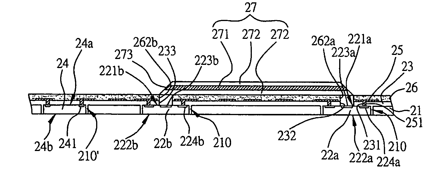
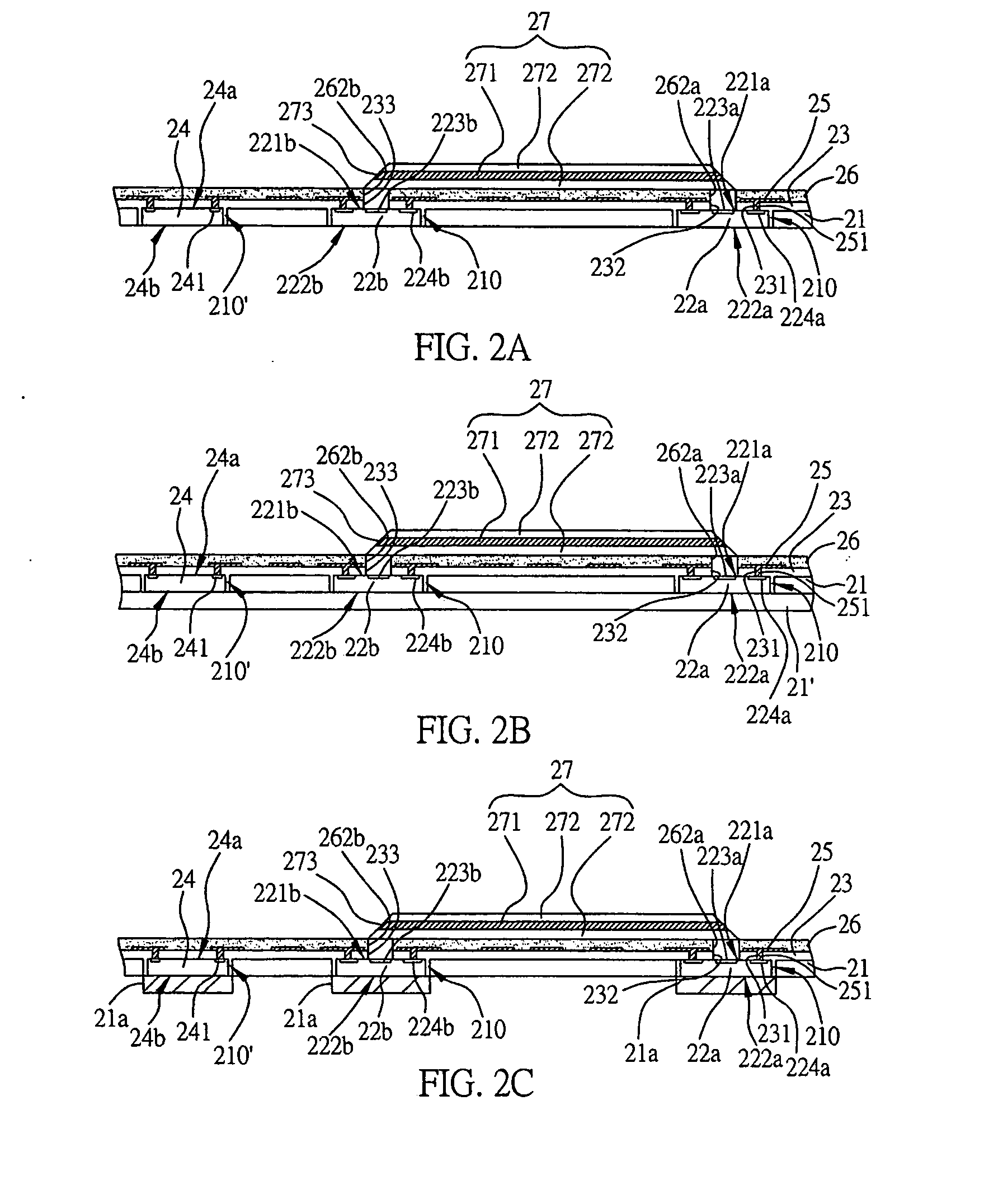
[0040] Referring to FIG. 2A, which is a cross-sectional diagram, illustrating the first embodiment of the present invention of the circuit board with optoelectronic component embedded therein, comprises: a carrier board 21 with at least two through openings 210, and the first and second optoelectronic components 22a, 22b are disposed in the openings 210 respectively; an dielectric layer 23 formed on the surface of the carrier board 21, the first and second optoelectronic components 22a, 22b; and a circuit layer 25 formed on the surface of the dielectric layer 23.
[0041] The carrier board 21 could be metal board, ceramic board, insulating board and organic circuit board, or any board mentioned here forming a stack structure freely; therein the organic circuit board is printed circuit board or IC packaging substrate. The use of metal board or ceramic board can be used as a heatsink for the first and second optoelectronic components 22a, 22b, or using the organic circuit board as the carrier board 21 can increase the electrical performance.
[0042] The first and second optoelectronic components 22a, 22b have active surfaces 221a, 221b and non-active surfaces 222a, 222b opposite to the active surfaces 221a, 221b respectively, and the active surfaces 221a, 221b have optical active areas 223a, 223b and a plurality of electrode pads 224a, 224b. The first and second optoelectronic components 22a, 22b could be an optical active component or an optical passive component, therein the optical active component includes laser diode (LD), light emitting diode (LED), or vertical cavity surface emitting laser (VCSEL), and the optical passive component includes photo diode or photo sensing component.
[0043] The dielectric layer 23 uses photosensitive resin or non-photosensitive such as ABF (Ajinomoto Build-up Film), BCB (Benzocyclo-Buthene), LCP (Liquid Crystal Polymer), PI (Poly-imide), PPE (Poly(phenylene ether)), PTFE (Poly(tetra-fluoroethylene)), FR4, FR5, BT (Bismaleimide Triazine) and Aramide, or a mixture of material PI and glass fiber; the dielectric layer 23 forms a plurality of vias 231 to expose the electrode pads 224a, 224b of the first and second optoelectronic components 22a, 22b and holes 232, 233 to expose the optical active areas 223a, 223b of the first and second optoelectronic components 22a, 22b.
[0044] The circuit layer 25 is formed on the surface of the dielectric layer 23 and electrically connected to the electrode pads 224a, 224b of the first and second optoelectronic components 22a, 22b through the electrically conductive structure 251 formed in the via 231 of the dielectric layer 23.
[0045] At least one semiconductor component 24 is further formed at another opening 210′ of the carrier board 21, and the semiconductor component 24 has an active surfaces 24a and a non-active surfaces 24b opposites to the active surface 24a, and the active surfaces 24a has a plurality of electrode pads 241, and the electrically conductive structure 251 of the circuit layer 25 is electrically connected to the electrode pads 241 of the semiconductor component 24.
[0046] Beside, an insulating protecting layer 26 is further formed on the surface of the dielectric later 23 and the circuit layer 25, to protect the circuit layer 25 covering underneath, and forms holes 262a, 262b to expose the optical active areas 223a, 223b of the first and second optoelectronic components 22a, 22b.
[0047] Furthermore, an optical transmission element 27 such as an optical waveguide is formed on the surface of the insulating protecting layer 26, and comprises a core layer 271 and a cladding layer 272 forming on the surface of the core layer 271, wherein the refraction rate of the optical signal in the core layer 271 is larger than in the cladding layer 272; at least one terminal of the optical transmission element 27 has a reflection surface 273 used to reflect the transmitted optical signal, and the reflection surface 273 is at the top of the hole 232 or 233, preferably, the reflection surface is at 45° to allow the optical signal traveling through the core layer 271 directly during transmission, avoiding several extra reflections between the core layer 271 and the cladding layer 272 boundary, which causes increasing in transmission distance and optical loss. At the present embodiment, the two terminals of the optical transmission element 27 both have a reflection surface 273 with 45°, where the two reflection surfaces are at the top of the two holes 232, 233, and opposite to the optical active areas 223a, 223b of the first and second optoelectronic components 22a, 22b respectively, to enable the optical transmission between the first and second optoelectronic components 22a, 22b. Because the first and second optoelectronic components transmit and receive the optical signal directly via the optical transmission element 27, which leads to shorten the transmission path, thereby reduces the signal loss during transmission and improves the transmission quality.
[0048] Additionally, the holes 232, 233 penetrating through the dielectric layer 23 and the holes 262a, 262b penetrating through the insulating protecting layer 26 could be filled up with light guiding material (not shown in the diagram) or extracted to vacuum to reduce the interference from the outside noise to improve the efficiency of the optical transmission.

Example

Second Embodiment
[0049] Referring to FIG. 2B, which is a cross-sectional diagram, illustrating the second embodiment of the present invention of the circuit board with optoelectronic component embedded therein, has a difference comparing to the previous embodiment. Another carrier board 21′ is attached to the bottom surface of the carrier board 21, and the carrier board 21′ could be metal board, ceramic board, insulating board and organic circuit board, or any board mentioned here forming a stack structure freely; therein the organic circuit board is printed circuit board or IC packaging substrate; and if the carrier board 21′ is made form metal board or ceramic board, the heat generated by the first and second optoelectronic components 22a, 22b and the semiconductor component 24 during operation can be diffused effectively, which strengthen the heat dissipation efficiency of the circuit board with optoelectronic component embedded therein.
[0050] Referring to FIG. 2C, a heatsink block 21a is disposed on the non-active surfaces 222a, 222b of the first and second optoelectronic components 22a, 22b at the opening 21 of the carrier board 21, and the non-active surface 24b of the semiconductor component 24 to diffuse the heat.

Example

Third Embodiment
[0051] Referring to FIG. 2D, a cross-sectional diagram illustrating the third embodiment of the present invention of the circuit board with optoelectronic component embedded therein, has a difference comparing to the previous embodiment, where a protecting shield such as an encapsulant 28 is formed on the optical transmission element 27 and the insulating protecting layer 26, to protect the optical transmission element 27 from damage by the outside influence, thereby increases the lifetime of the product.
[0052] Referring to FIG. 2E illustrating another embodiment of the optical transmission element protection of the present invention, where a protecting shield such as metallic case 28′ is formed on the optical transmission element 27 and the insulating protecting layer 26, to protect the optical transmission element 27.

PUM

no PUM

Description & Claims & Application Information

We can also present the details of the Description, Claims and Application information to help users get a comprehensive understanding of the technical details of the patent, such as background art, summary of invention, brief description of drawings, description of embodiments, and other original content. On the other hand, users can also determine the specific scope of protection of the technology through the list of claims; as well as understand the changes in the life cycle of the technology with the presentation of the patent timeline. Login to view more.

Similar technology patents

Heat sink fabrication method

InactiveUS20130319064A1Simplify fabrication processReduce tooling costSemiconductor/solid-state device detailsSolid-state devicesHeat sinkRadiation
Owner:DONG GUAN YUNG TENG ELECTRONICS PROD

Method for fabricating memory device

ActiveUS9070753B1Reduce process variation and fabricating costSimplify fabrication processSolid-state devicesSemiconductor/solid-state device manufacturingPhysicsMask layer
Owner:MACRONIX INT CO LTD

Projection system and light-homogenizing device adjustment element

ActiveUS20140185022A1Decrease number of componentSimplify fabrication processProjectorsColor television detailsProjection systemActuator
Owner:CORETRONIC

Classification and recommendation of technical efficacy words

  • Simplify fabrication process
  • Reduces fabrication difficulty

Method of fabricating organic light emitting display

InactiveUS20050264184A1Improve reliability of displaySimplify fabrication processDischarge tube luminescnet screensElectroluminescent light sourcesOptoelectronicsElectrode
Owner:SAMSUNG DISPLAY CO LTD
Why Eureka
Try Eureka