The second established variant, which is substantially faster than the first variant, requires greater capital costs.
In order to achieve this high welding speed, the capital costs are correspondingly high.
The deposition power in this method is usually 5.9 kg per hour, so that this method is the fastest but also the most expensive orbital welding method compared with the preceding ones.
Furthermore, the
doors of the welding tent are secured in such a way that no access by unauthorised persons from the outside is possible during the welding work.
MAG orbital welding has encountered its limits through high repair rates, downtimes due to weather influences and impairment of the weld seam quality due to the operator.
Welding parameters which fully automatically influence the
welding process in the various welding positions have the
disadvantage that external changes—in particular splashes which can form in an uncontrolled manner during welding—or atmospheric influences—require the welder to intervene immediately in the automated process and manipulate the
welding process in order to minimise the errors.
The welding of the root using internal MAG orbital welding heads is very fast but also very expensive.
Moreover, the root layer is often associated with very many welding defects.
The high capital costs and the large number of well trained personnel required have therefore prevented this method from achieving a breakthrough.
These problems have become even more extensive when two or four wires are used on a welding head.
This leads not only to considerable capital costs but also results in a major maintenance effort and high personnel costs, since each welding
station has to be operated by appropriately qualified personnel.
The beam guidance in the case of such CO2 lasers must be effected by means of relatively complicated optical mirror systems since beam guidance by means of a flexible
waveguide is not possible owing to the
wavelength of the
laser light emitted.
By using
diode arrays for excitation instead of arc lamps, an increase in the efficiency by 3% for a lamp-pumped
system up to about 10% is possible, but with considerably higher capital costs.
However, its beam power is currently limited to 4 kW.
However, these four laser beam sources used in the case of
laser beam welding have not been successfully used to date in the mobile orbital welding of pipes, in particular pipelines.
Since the beam emitted by a CO2 laser can be deflected only by means of mirrors and the beam guidance is thus extremely difficult, CO2 lasers have been used to date in practice only in stationary operation or in the off-
shore sector on ships, either the pipes to be joined being rotated relative to the stationary laser beam in the case of a stationary laser
beam source or the entire laser
beam source being pivoted by means of a stable device about the upright stationary pipe.
Pivoting of the entire CO2 laser about a horizontal pipe by means of mobile devices is not possible with the required precision under
field conditions owing to the great weight and the size of a high-power CO2 laser.
Guidance of the laser beam around a stationary pipe, preferably through more than 180°, so that the beam always strikes the outer surface of the pipe substantially perpendicularly is very complicated since mirror systems having a multiplicity of joints have to be used.
Common to the known mirror systems is that, owing to the large space requirement, the great weight, the high capital costs and the high sensitivity with respect to soiling, misadjustment or damage to the mirrors, they are unsuitable for mobile use under
field conditions.
Internal circumferential welding by means of a CO2 laser beam coaxial with the pipe axis is possible, but to date only unsatisfactory results have been achieved by internal circumferential welding of pipelines without additional external circumferential welding.
A further problem of the CO2 laser is its poor efficiency and the associated
high energy and cooling requirement.
Since power has to be generated as a rule by mobile generators in field use, sufficient power supply for high-powered CO2 lasers is problematic.
Furthermore, owing to the great evolution of heat, it is necessary to use large cooling systems, which additionally complicate the mobile use of a CO2 laser.
Owing to the relatively high sensitivity of a CO2 laser to vibrations, mobile use is scarcely possible.
Owing to the suitability of the emitted laser beam for beam guidance via a flexible
waveguide, an Nd:YAG laser would be suitable for guiding the beam around a pipe of large
diameter but this
laser source, like the CO2 laser proves to be unsuitable for mobile field use.
Owing to the poor efficiency of an Nd:YAG laser compared with other industrial lasers, the power supply and the space requirement of the laser and its additional components, in particular the cooler, present a still unsolved problem for use in the mobile orbital welding of pipelines.
Moreover, no completely satisfactory welding results have been achieved to date even in stationary use with the Nd:YAG laser, owing to the lower laser beam power compared with the CO2 laser, since the maximum achievable welding speed in the welding of large pipes, in particular for a pipeline, is too low and single-pass welding cannot be effected.
The beam power of the disc laser is currently limited to not more than 4 kW which, in view of the beam properties of a disc laser, is to be regarded as insufficient for the orbital welding of the thick-walled pipes.
In
spite of its high efficiency in the region of 20% and the associated relatively low power requirement, the disc laser is currently by no means suitable as a mobile
laser source which is inevitably exposed to vibrations under
field conditions, owing to its design which is difficult to adjust and its extremely high sensitivity to vibrations.
However, owing to its fundamental lower beam intensity and beam power the
diode laser as a rule does not permit deep welding under
normal conditions so that the welding of thick-walled pipes will be possible only by the multi-pass technique.
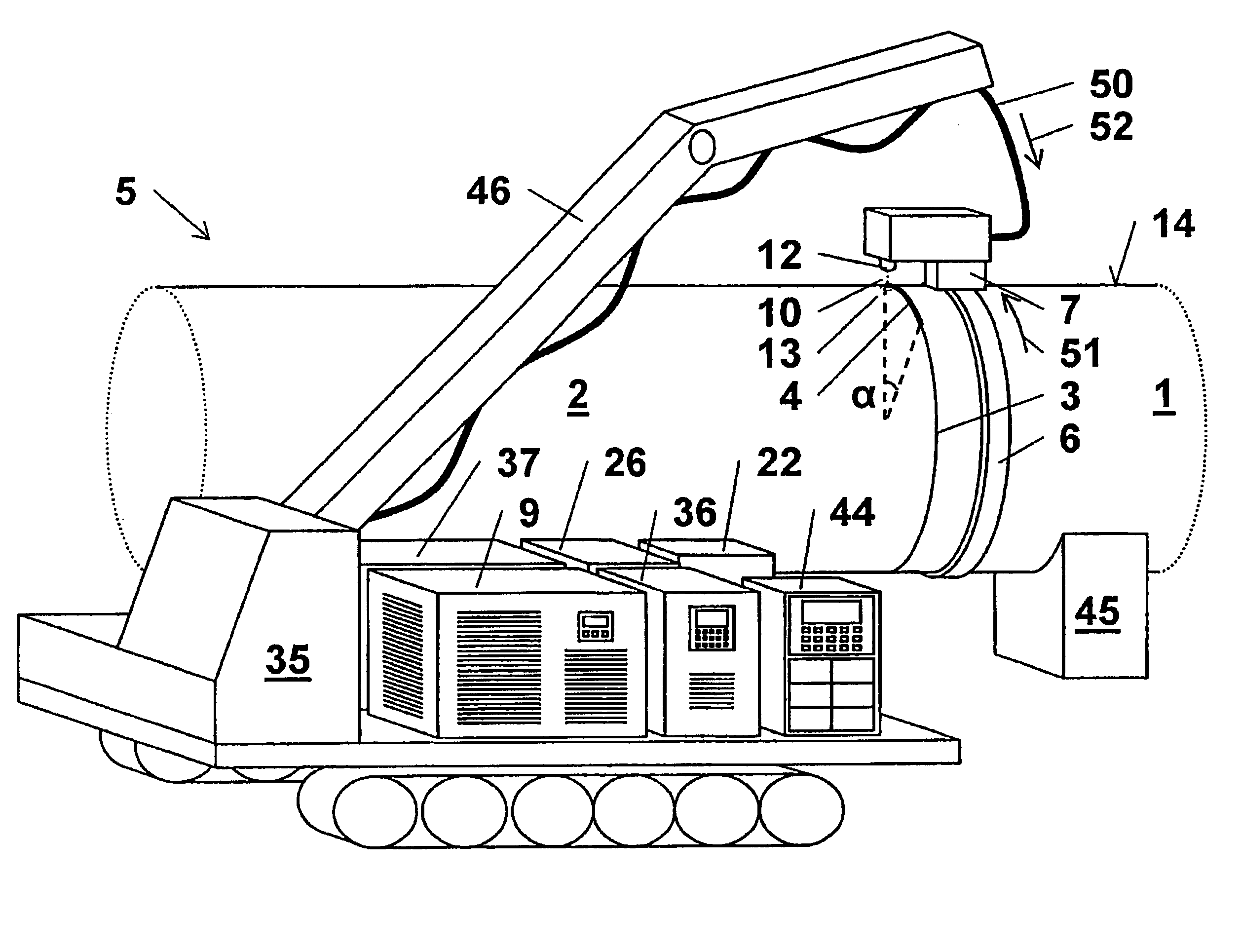
Since the laser beam source is arranged directly on the welding vehicle and has to be moved around the entire pipe, considerable limitations in the choice of a beam source suitable for this purpose result.
A
diode laser would under certain circumstances be suitable with regard to its size for direct mounting on the transport carriage, but, owing to its fundamental low beam intensity, it does not permit deep welding of thick-walled pipes without the use of the mulfi-pass technique.
The use of such a welding method for the welding of long pipes of large
diameter up to more than 1500 mm and wall thicknesses of up to about 25 mm, for example pipelines, at high welding speed is not possible by means of the welding device described, which is designed only for low laser powers.
The guidance of the laser beam of a CO2
laser source by means of a fibre optic cable, as described in U.S. Pat. No. 5,601,735, is not possible with the use of a high-power CO2 laser source having a laser power of more than 1 kW.

