Electroluminescent device containing a phenanthroline derivative

a technology of electroluminescent devices and derivatives, which is applied in the direction of organic semiconductor devices, discharge tube luminescnet screens, natural mineral layered products, etc., can solve the problems of shortening the life of the device, limiting many desirable applications, etc., and achieves good device stability, reduce drive voltage, and increase luminance

Inactive Publication Date: 2007-05-31
GLOBAL OLED TECH
View PDF79 Cites 34 Cited by
  • Summary
  • Abstract
  • Description
  • Claims
  • Application Information

AI Technical Summary

Benefits of technology

[0010] The invention provides an OLED device comprising a cathode, an anode, and a light-emitting layer therebetween, additionally comprising a layer between the cathode and the light-emitting layer including a phenanthroline compound comprising no more than two optionally substituted phenanthroline moieties wherein one and only one group substituted on a phenanthroline nucleus includes an aromatic system comprising four or more fused aromatic rings. Such a device provides desirable electroluminescent properties, such as increased luminance and reduced drive voltage, as well as good device stability.

Problems solved by technology

While organic electroluminescent (EL) devices have been known for over two decades, their performance limitations have represented a barrier to many desirable applications.
However, although some of these phenanthroline materials may provide increased luminance and reduced drive voltage in an OLED device, device lifetimes may be shorter than desired.

Method used


Image

  • Electroluminescent device containing a phenanthroline derivative
  • Electroluminescent device containing a phenanthroline derivative
  • Electroluminescent device containing a phenanthroline derivative

Examples


example 1

Synthesis of Inv-1[2-(1 -pyrenyl)-1,10-phenanthroline].

[0158] The synthesis of Inv-I was based on a procedure described by E. C. Riesgo et al., J. Org. Chem., 61, 3017-22, (1996). 1-Acetylpyrene (2.0 g, 8.2 mmol), 8-amino-7-quinolinecarbaldehyde (Int-C, Scheme I, 1.4 g, 8.2 mmol) and anhydrous ethanol (500 ml) were placed into a round-bottom flask under a nitrogen atmosphere. Saturated ethanolic potassium hydroxide (8.6 ml) was added dropwise. The mixture was then heated to reflux for 2 days. Thin layer chromatography (Baker-flex® Aluminum Oxide IB-F) using methylene chloride as eluent showed that both starting materials had reacted. Ethanol was removed by rotary evaporation, methylene chloride (200) and water (150 ml) were added and, after separation, most of the methylene chloride was removed. Hexanes (75 ml) was added and the remaining methylene chloride was removed. The precipitated solid was collected by filtration and washed with hexanes to give a brown solid. The brown soli...

example 2

[0159] Fabrication of Device 1-1, 1-2, and 1-3.

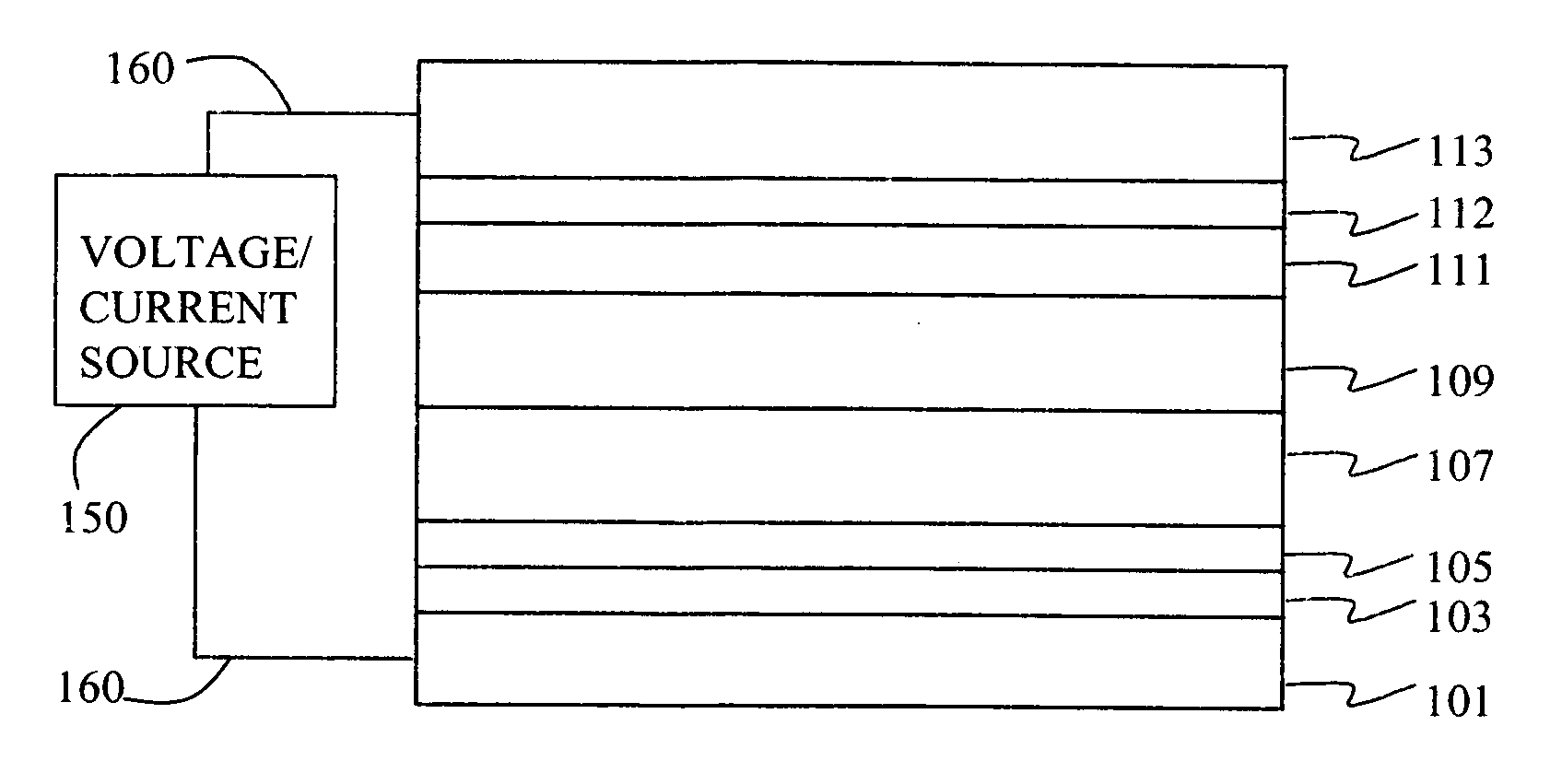
[0160] Device 1-1, 1-2, and 1-3 were prepared in the following manner. A ˜1.1 mm thick glass substrate coated with a transparent ITO conductive layer was cleaned and dried using a commercial glass scrubber tool. The thickness of ITO is about 25 nm and the sheet resistance of the ITO is about 68 Ω / square. The ITO surface was subsequently treated with oxidative plasma to condition the surface as an anode. A layer of CFx, 1 nm thick, was deposited on the clean ITO surface by decomposing CHF3 gas in an RF plasma treatment chamber. The substrate was then transferred into a vacuum deposition chamber for deposition of all other layers on top of the substrate. The following layers were deposited in the following sequence by sublimation from heated boats under a vacuum of approximately 10−6 Torr: [0161] a) a hole-transporting layer of either 75 nm of N,N′-di(1 -naphthyl)-N,N′-diphenyl-4,4′-diaminobiphenyl (NPB); [0162] b) a 20 nm light-emitting...


PUM

PropertyMeasurementUnit
thickaaaaaaaaaa
operating voltagesaaaaaaaaaa
thicknessaaaaaaaaaa

Abstract

An OLED device comprises a cathode, an anode, and a light-emitting layer therebetween, and additionally comprises a layer between the cathode and the light-emitting layer including a phenanthroline compound comprising no more than two optionally substituted phenanthroline moieties wherein one and only one group substituted on a phenanthroline nucleus includes an aromatic system comprising four or more fused aromatic rings. Such a device provides desirable electroluminescent properties, such as increased luminance and reduced drive voltage, as well as good device stability.

Description

FIELD OF THE INVENTION [0001] This invention relates to organic electroluminescent devices. More specifically, this invention relates to devices that emit light from a current-conducting organic layer and that include a certain phenanthroline derivative in one layer between the cathode and the light-emitting layer. BACKGROUND OF THE INVENTION [0002] While organic electroluminescent (EL) devices have been known for over two decades, their performance limitations have represented a barrier to many desirable applications. In simplest form, an organic EL device is comprised of an anode for hole injection, a cathode for electron injection, and an organic medium sandwiched between these electrodes to support charge recombination that yields emission of light. These devices are also commonly referred to as organic light-emitting diodes, or OLEDs. Representative of earlier organic EL devices are Gurnee et al. U.S. Pat. No. 3,172,862, issued Mar. 9, 1965; Gurnee U.S. Pat. No. 3,173,050, issu...

Claims


Application Information

Patent Timeline
Patent Type & Authority Applications(United States)
IPC IPC(8): H01L51/54
CPCH01L51/0054H01L51/0056H01L51/0057H01L51/0058H01L51/0072H01L51/008H01L51/0081H01L51/5048H01L2251/308H10K85/624H10K85/625H10K85/622H10K85/626H10K85/322H10K85/324H10K85/6572H10K50/14H10K2102/103
Inventor KLUBEK, KEVINKONDAKOV, DENIS
Owner GLOBAL OLED TECH
Why Eureka
Try Eureka