Electrolysis vessel and apparatus for generating electrolyzed water

a technology of electrolysis vessel and electrolysis apparatus, which is applied in the direction of electrolysis components, chemistry apparatus and processes, water/sludge/sewage treatment, etc., can solve the problems of low electrolysis efficiency relative to applied power, inability to fully improve electrolysis efficiency relative to applied voltage, and increase in equipment siz

Inactive Publication Date: 2007-06-14
HONDA MOTOR CO LTD
View PDF6 Cites 19 Cited by
  • Summary
  • Abstract
  • Description
  • Claims
  • Application Information

AI Technical Summary

Benefits of technology

[0028] The electrolyzed water producing equipment of the present invention is characterized by that electrolyzed water is produced using the above-described electrolysis cell. The electrolyzed water

Problems solved by technology

The above-described constitution however is accompanied by the problem that an electrical resistance between the electrodes is large owing to a wide space between the electrodes disposed with the membrane interposed therebetween and an electrolysis efficiency is therefore low relative to the applied power.
In the above-described electrolysis cell, however, a circulation resistance is high because the raw water is circulated inside of the porous electrode base material and an increase in the production amount of electrolyzed water per hour inevitably leads to a size increase of the equipment.
In addition, in the above-described electrolysis cell

Method used


Image

  • Electrolysis vessel and apparatus for generating electrolyzed water
  • Electrolysis vessel and apparatus for generating electrolyzed water
  • Electrolysis vessel and apparatus for generating electrolyzed water

Examples


example 1

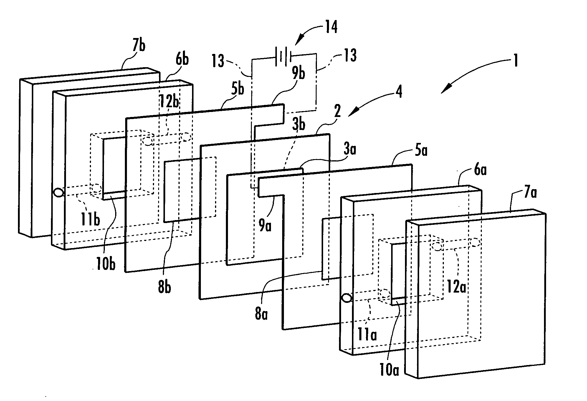
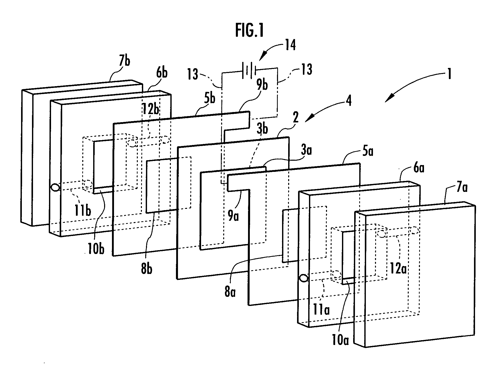
[0050] In this Example, the area of the electrodes 3a and 3b facing the electrolysis rooms 10a and 10b was set at 16 cm2. Distilled water and brine (aqueous solution of sodium chloride) having a concentration of 0.8 g / L were fed to the electrolysis room 10a on the anode side and the electrolysis room 10b on the cathode side, respectively each at a flow rate of 16 mL / min and a constant current of 0.5 A was applied to the electrodes 3a and 3b to effect electrolysis.

[0051] At the time, the voltage was approximately 7V, acidic electrolyzed water produced in the electrolysis room 10a had a pH of 1.94 and an effective chlorine concentration was 50 ppm. The results are shown in Table 1.

[0052] The above-described effective chlorine concentration was determined by adding 0.5 mL of a 0.1 mole / L silver nitrate solution dropwise to 5 mL of the acidic electrolyzed solution to form a white precipitate of silver chloride and measuring the amount of transmitted light of the turbid solution. The s...

example 2

[0061] In this Example, a paste mixture was prepared by mixing an electrode base material, a catalyst and a binder at a weight ratio of 100:5:7. Titanium carbide (TiC) of 325 mesh or less was used as the electrode base material, while a 3:7 (weight ratio) mixture of platinum black and iridium black was used as the catalyst. As the binder, a solution obtained by dissolving polyvinyl alcohol having a saponification ratio of 100% in a water / ethanol mixed solvent (volumetric ratio, 1:1) at a concentration of 2 wt. % was used. The paste mixture had a viscosity of from 15 to 25 cps.

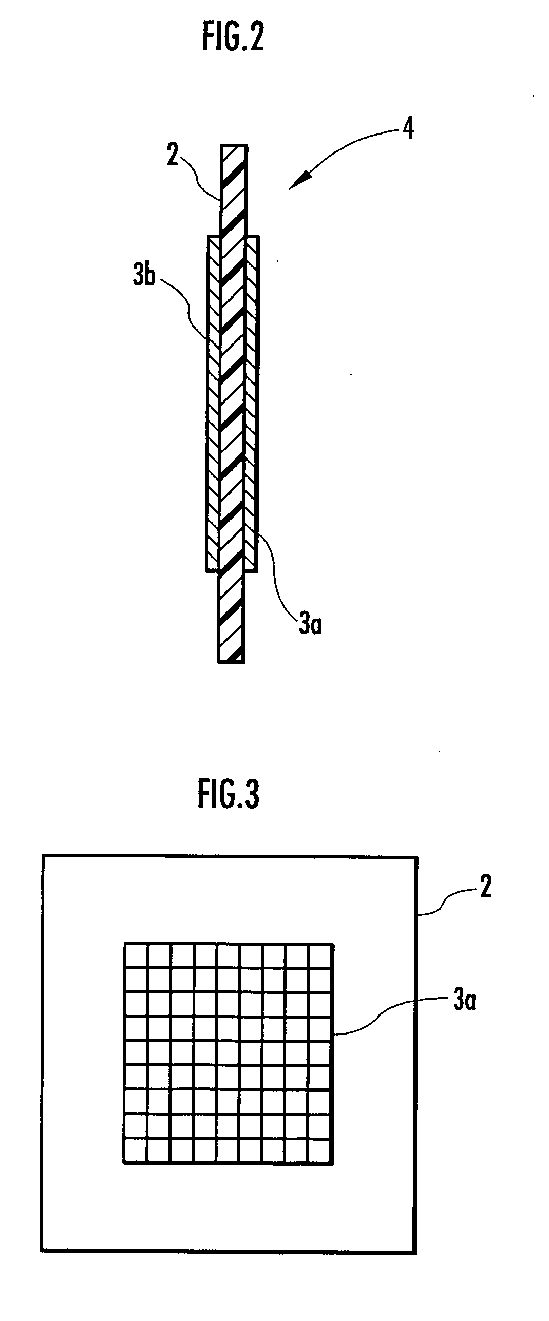
[0062] A membrane-electrode structure 4 was then formed by applying the paste mixture onto an anion exchange membrane (“Selemion (trade name) AMV”, product of Asahi Glass) having a thickness of about 100 μm, which was used as the ion permeable membrane 2, drying, and heating and pressurizing at 80° C. and 10 MPa for 30 minutes. As a result of measurement of the surface resistance of the electrolyzed water prod...


PUM

PropertyMeasurementUnit
Sizeaaaaaaaaaa
Electrical conductoraaaaaaaaaa
Electric potential / voltageaaaaaaaaaa

Abstract

Provided is an electrolysis cell and an electrolyzed water producing equipment which are each small in size, has excellent electrolysis efficiency and can reduce an anion concentration in acidic electrolyzed water. The electrolysis cell is equipped with electrolysis rooms 10a and 10b located opposite to each other via an ion permeable membrane 2, raw water supply units 11a and 11b, electrodes 3a and 3bdisposed with the membrane interposed therebetween, and electrolyzed water discharge units 12a and 12b. The membrane 2 is an anion permeable film. The electrodes 3a and 3b are formed so as to firmly adhere to both surfaces of the anion permeable membrane 2 and expose a portion of the anion permeable membrane 2. Only raw water fed to the electrolysis room 10b on the cathode side contains an electrolyte. The electrodes 3a and 3b are porous and they each has an electrode base material made of a powdery titanium compound such as TiC or TiN, a catalyst such as platinum black or iridium black and a binder such as PVA. The electrodes 3a and 3b may be mesh-shaped or comb-shaped. The electrodes 3a and 3b are formed by applying a conductive paste containing conductive powders onto the surfaces of the anion permeable membrane 2, followed by heating or pressurization.

Description

TECHNICAL FIELD [0001] The present invention relates to an electrolysis cell for electrolyzing raw water fed to a pair of electrolysis rooms located opposite to each other via an ion permeable membrane by applying a voltage to a pair of electrodes disposed in the electrolysis rooms, respectively, via the membrane; and an electrolyzed water producing equipment for generating electrolyzed water by using the electrolysis cell. BACKGROUND ART [0002] As an electrolyzed water producing equipment, known are equipments for producing electrolyzed water by using an electrolysis cell equipped with a pair of electrolysis rooms located opposite to each other via an ion permeable membrane and a pair of electrodes disposed in the respective electrolysis rooms with the membrane interposed therebetween. In the above-described electrolyzed water producing equipment, raw water containing an electrolyte is fed to each of the electrolysis rooms and a voltage is applied to the pair of electrodes to elect...

Claims


Application Information

Patent Timeline
IPC IPC(8): C25B1/06
CPCC02F1/4674C02F2001/46142C02F2001/46161C02F2201/46115C25B9/10C25B9/23
Inventor MIYASHITA, KOHICHI
Owner HONDA MOTOR CO LTD
Why Eureka
Try Eureka