
RF plasma-enhanced deposition of fluorinated films

a fluorinated film, enhanced technology, applied in the direction of plasma technique, transportation and packaging, synthetic resin layered products, etc., can solve the problems of reducing the efficiency of the molecular recognition process, teflon is not soluble in any solvent, and the adhesion of teflon particles suspended in organic and inorganic media and teflon-like materials dissolved in organic solvents are often not satisfactory, so as to prevent or minimize surface oxid

Inactive Publication Date: 2007-07-26
WISCONSIN ALUMNI RES FOUND
View PDF9 Cites 27 Cited by
  • Summary
  • Abstract
  • Description
  • Claims
  • Application Information

AI Technical Summary

Benefits of technology

[0008] The fluorinated films deposited using the methods provided herein may be fabricated with lower oxygen content than similar surfaces fabricated using other plasma-mediated deposition techniques that lack an in situ active site quenching step. In addition, unlike similar surfaces made using spin coating techniques, the fluorinated films are strongly bound to the surface. The fluorinated films are hydrophobic and provide very low fluorescence background.
[0009] The fluorinated films provided herein are well suited for use as coatings in chemical and biochemical sensors where low fluorescence background is important. Such sensors include biochips and biosensors, including flexible, thin-film biosensors that can be integrated into traditional microelectronics and used in fluorescence assays. The fluorinated films are also well suited for use as coatings on implantable medical devices where low friction, hydrophobic surfaces are important. For example, the coatings may be applied to catheter guide wires to prevent sticking of the guide wires to the catheter surface.
[0010] In a first step of the methods provided herein, the surface of a substrate is exposed to a plasma of fluorine-containing fragment molecules generated from fluorinated precursor molecules under conditions that promote the deposition of a crosslinked fluorinated film on the surface of the substrate. In a subsequent step, plasma generated active sites (e.g., ion and free radicals) on the surface are reacted with molecules of a fluorinated quenching molecule (which may or may not be same as the fluorinated precursor molecule used to generate the fluorine-containing fragment molecules) in situ, in the absence of plasma, to quench the surface active sites and prevent or minimize surface oxidation.

Problems solved by technology

However, Teflon is not soluble in any solvents and modified poly-tetrafluoroethylene macromolecular chains are shy on certain including thermal stability and hydrophobic character.
Adhesion of Teflon particles suspended in organic and inorganic media and Teflon-like materials dissolved in organic solvents is often not satisfactory due to the inert nature of the perfluorinated macromolecular chains that create poor adhesion characteristics of the deposited layers.
These oxygen containing groups increase the surface energy of the deposited layers and generate reactive surfaces, which significantly reduce the efficiency of the molecular recognition process.

Method used


Image

  • RF plasma-enhanced deposition of fluorinated films
  • RF plasma-enhanced deposition of fluorinated films
  • RF plasma-enhanced deposition of fluorinated films

Examples


example 1

Production of a Fluorinated Thin Film on a Stainless Steel Substrate Using HFPO as a Precursor Gas.

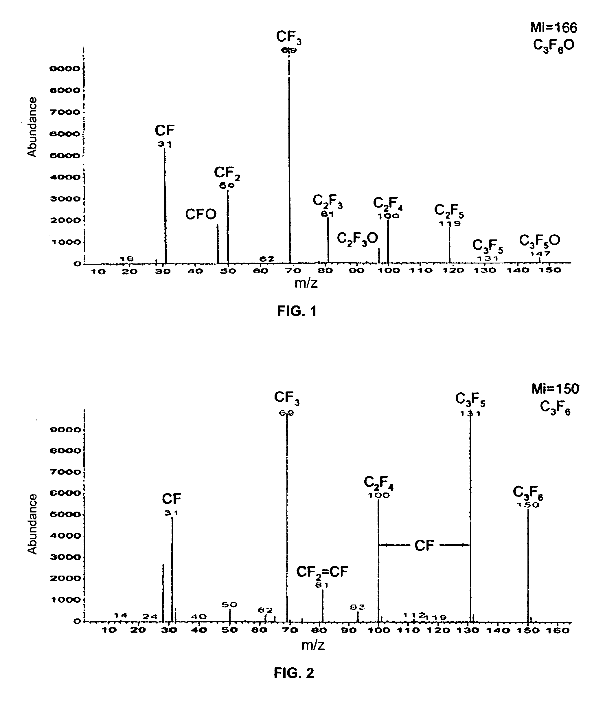
[0052] A fluorinated film was deposited on a stainless steel substrate using precursor molecules of HFPO. The RF plasma parameters during the initial plasma-mediated deposition step were as follows: 1) precursor gas pressure=200 Torr; 2) period=1000 msec; duty=30%; power=100 Watts; and plasma exposure time=5 minutes. The surface active sites on the resulting fluorinated film were quenched using a post-plasma environment of HFPO at a pressure of 1 Torr for about 30 minutes. ESCA analysis of the resulting hydrophobic fluorinated surface film revealed a carbon content of 38.5 atomic percent, a fluorine content of 60 atomic percent and an oxygen content of 1.5 atomic percent. The water contact angle on the hydrophobic surface film was 116°.

example 2

Production of a Fluorinated Thin Film on a Stainless Steel Substrate Using HFPO as a Precursor Gas.

[0053] A fluorinated film was deposited on a stainless steel substrate using precursor molecules of HFPO. The RF plasma parameters during the initial plasma-mediated deposition step were as follows: 1) precursor gas pressure=200 Torr; 2) period=1000 msec; duty=15%; power=100 Watts; and plasma exposure time=5 minutes. The surface active sites on the resulting fluorinated film were quenched using a post-plasma environment of HFPO at a pressure of 1 Torr for about 30 minutes. ESCA analysis of the resulting hydrophobic fluorinated surface film revealed a carbon content of 37.3 atomic percent, a fluorine content of 61.3 atomic percent and an oxygen content of 1.4 atomic percent. The water contact angle on the hydrophobic surface film was 115°.

example 3

Production of a Fluorinated Thin Film on a Stainless Steel Substrate Using HFPP as a Precursor Gas.

[0054] A fluorinated film was deposited on a stainless steel substrate using precursor molecules of HFPP. The RF plasma parameters during the initial plasma-mediated deposition step were as follows: 1) precursor gas pressure=200 Torr; 2) period=800 μsec; duty=30%; power=100 Watts; and plasma exposure time=5 minutes. The surface active sites on the resulting fluorinated film were quenched using a post-plasma environment of HFPP at a pressure of 1 Torr for about 30 minutes. ESCA analysis of the resulting hydrophobic fluorinated surface film revealed a carbon content of 41.7 atomic percent, a fluorine content of 57.5 atomic percent and an oxygen content of 0.8 atomic percent. The water contact angle on the hydrophobic surface film was 114°.


PUM

PropertyMeasurementUnit
Fractionaaaaaaaaaa
Water contact angleaaaaaaaaaa
Percent by atomaaaaaaaaaa

Abstract

Low- or atmospheric pressure RF plasma-enhanced thin film deposition methods are provided for the deposition of hydrophobic fluorinated thin films onto various substrates. The methods include at least two steps. In the first step, RF plasma-mediated deposition is used to deposit a fluorinated film onto a substrate surface. In a second step, plasma-generated active sites on the fluorinated film are quenched by reacting them with stable fluorinated gas-phase molecules in situ, in the absence of plasma, to provide a hydrophobic fluorinated thin film having a very low oxygen content. In some instances the hydrophobic fluorinated thin films have an atomic oxygen concentration of no more than about 3%.

Description

STATEMENT OF GOVERNMENT RIGHTS [0001] Research funding was provided for this invention by the Office of Naval Research (ONR) under Grant Number N00014-02-1-0893. The United States government has certain rights in this invention.FIELD OF THE INVENTION [0002] This invention pertains generally to the radiofrequency (RF) plasma enhanced deposition of fluorinated thin films. BACKGROUND OF THE INVENTION [0003] Use of low fluorescence background (LFB) substrates for Raman Spectroscopy investigations is crucial for the generation of high-resolution Raman spectra. Equally significant is the fact that the LFB substrates should exhibit an advanced hydrophobic character that eliminates the spread of the deposited analyte-spots and renders as a result small (concentrated) analyte surface areas. LFB is also a concern for biosensor and large surface area bio-array applications where the desired molecular recognition sites, the ordered spots of the network, should not “communicate” and should retai...

Claims


Application Information

Patent Timeline
IPC IPC(8): H05H1/24B32B27/00
CPCB05D1/62C23C16/26B05D5/083B05D3/0453Y10T428/3154
Inventor DENES, FERENCZ S.MANOLACHE, SORIN O.CRUZ-BARBA, LUIS EMILIOLAGALLY, MAX G.
Owner WISCONSIN ALUMNI RES FOUND
Learn More