
Switch lighting el sheet and lighting switch and electronic apparatus using it

Inactive Publication Date: 2007-08-02
TOSHIBA MATERIALS CO LTD +1
View PDF6 Cites 9 Cited by
  • Summary
  • Abstract
  • Description
  • Claims
  • Application Information

AI Technical Summary

Benefits of technology

[0011] An object of the present invention is to provide a switch illuminating EL sheet capable of repetitively suppressing wire breakage and failure to light due to keystroke stress or the like without impairing reliability and clicking feeling of a key switch, when being used as an illumination light source or the like for a key switch. Further, another object of the present invention is to provide an illuminated switch in which wire breakage and failure to light due to keystroke stress or the like are suppressed without impairing reliability and clicking feeling, and an electronic apparatus using such an illuminated switch.

Problems solved by technology

Incidentally, for mobile communication apparatuses such as a cellular phone and PDA, there is a strong demand to make a key switch thinner, and therefore a LED cannot be arranged under a key top.
However, since the conventional illumination structure is not illumination from immediately under the key top, there are problems such that it is difficult to illuminate the key top portion evenly with adequate brightness, and that the structure becomes thick.
However, according to results of experiments and considerations conducted by the present inventors, it is revealed that conventional EL sheets have weak points such as failure to illuminate after a short period of time due to keystroke stress from a key top, and malfunction of a switch and impairment of clicking feeling (feeling of pressing a switch) due to the stiffness of the EL sheet.
A deposited film of ITO has high light transmittance and high conductivity, but also has defects such as breaking easily by extension / contraction or increasing its electric surface resistance due to mechanical stress or heats.
Accordingly, it is revealed that when the EL sheet is bent due to keystroke stress from a key top, a crack is generated in an ITO electrode, which easily causes increase in resistance value, wire breakage and failure to illuminate.
According to experiments conducted by the present inventor and others, by increasing the thickness of a base film of the ITO film, it is possible to suppress for a certain degree the failure of the EL sheet to illuminate, but in this case reliability and clicking feeling of the key switch are impaired.
Therefore, it is difficult to produce the EL sheet using a thin base material.
It is found that all of these can be a cause of impairing the clicking feeling.
Further, a problem also arises such that a black dot is often generated on the EL sheet during illumination in a high-humidity environment.
Both of them use a deposited film of ITO for the transparent electrode layer, and thus problems such as wire breakage and increase in surface resistance due to the deposited film of ITO are not solved.

Method used


Image

  • Switch lighting el sheet and lighting switch and electronic apparatus using it
  • Switch lighting el sheet and lighting switch and electronic apparatus using it

Examples


example 1

[0053] First, a ZnS-based EL phosphor was produced as follows. Specifically, 1 L (liter) of pure water was added to 100 g of zinc sulfide powder having a particle diameter of approximately 1 μm to 3 μm to make slurry, to which 0.25 g of copper sulfate (5 hydrates) and 40 g off magnesium chloride, 40 g of barium chloride, 20 g of sodium chloride were added as crystal growth agents (flux) and mixed them adequately. This slurry mixture was dried, filled in a quartz crucible and burned for four hours at a temperature of 1150° C. in the air.

[0054] Next, the above-described burned matter was subjected to washing and drying processing, and thereafter 15 g of zinc oxide was mixed per 300 g of the burned matter, and this mixture was filled in a quartz crucible and burned for 1.5 hour at a temperature of 750° C. in the air. This burned matter was dispersed into pure water and washed three times. Further, acid washing with a condition of pH=1.5 and neutralizing washing with pure water were pe...

example 2

[0058] Similarly to the above-described example 1, first a ZnS:Cu phosphor having a 50% D value of 26.3 μm was produced. This phosphor powder was re-sifted by a 500-mesh sifter to obtain a target EL phosphor. The particle distribution of this EL phosphor (ZnS:Cu phosphor) was measured similarly to the example 1. When a 50% D value was obtained as a mean particle diameter from results of this particle distribution measurements the 50% D value was 22.9 μm. Also, a ratio of coarse particle constitutes having a particle diameter of 25.4 μm or larger was 29.6% by mass. Except using this EL phosphor (ZnS:Cu phosphor) a switch illuminating EL sheet was produced similarly to the example 1. This switch illuminating EL sheet was subjected to the later-described characteristics evaluation.

example 3

[0059] Similarly to the above-described example 1, first a ZnS:Cu phosphor having a 50% D value of 26.3 μm was produced. This phosphor powder was re-sifted by a 635-mesh sifter to obtain a target EL phosphor. The particle distribution of this phosphor (ZnS:Cu phosphor) was measured similarly to the example 1. Results of the particle distribution measurement are as shown in Table 1. When a 50% D value was obtained as a mean particle diameter from results of this particle distribution measurement, the 50% D value was 19.3 μm. Also, a ratio of coarse particle constitutes having a particle diameter of 25.4 μm or larger was 14.4% by mass. Except using this EL phosphor (ZnS:Cu phosphor), a switch illuminating EL sheet was produced similarly to the example 1. This switch illuminating EL sheet was subjected to the later-described characteristics evaluation.


PUM


Abstract

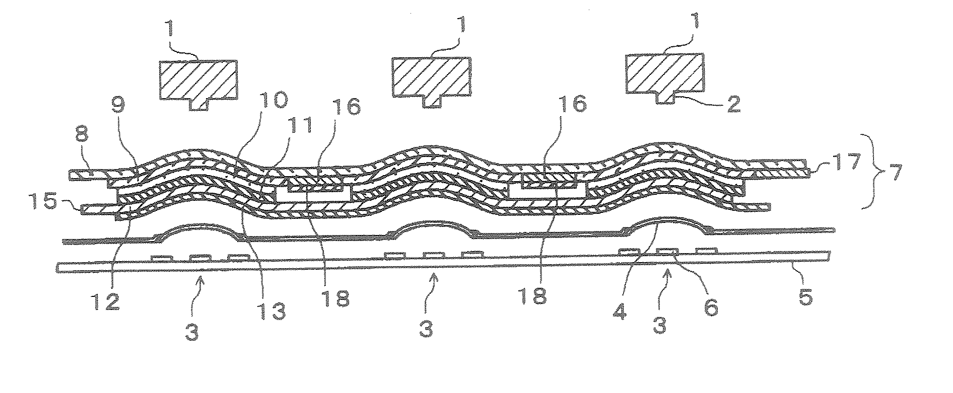
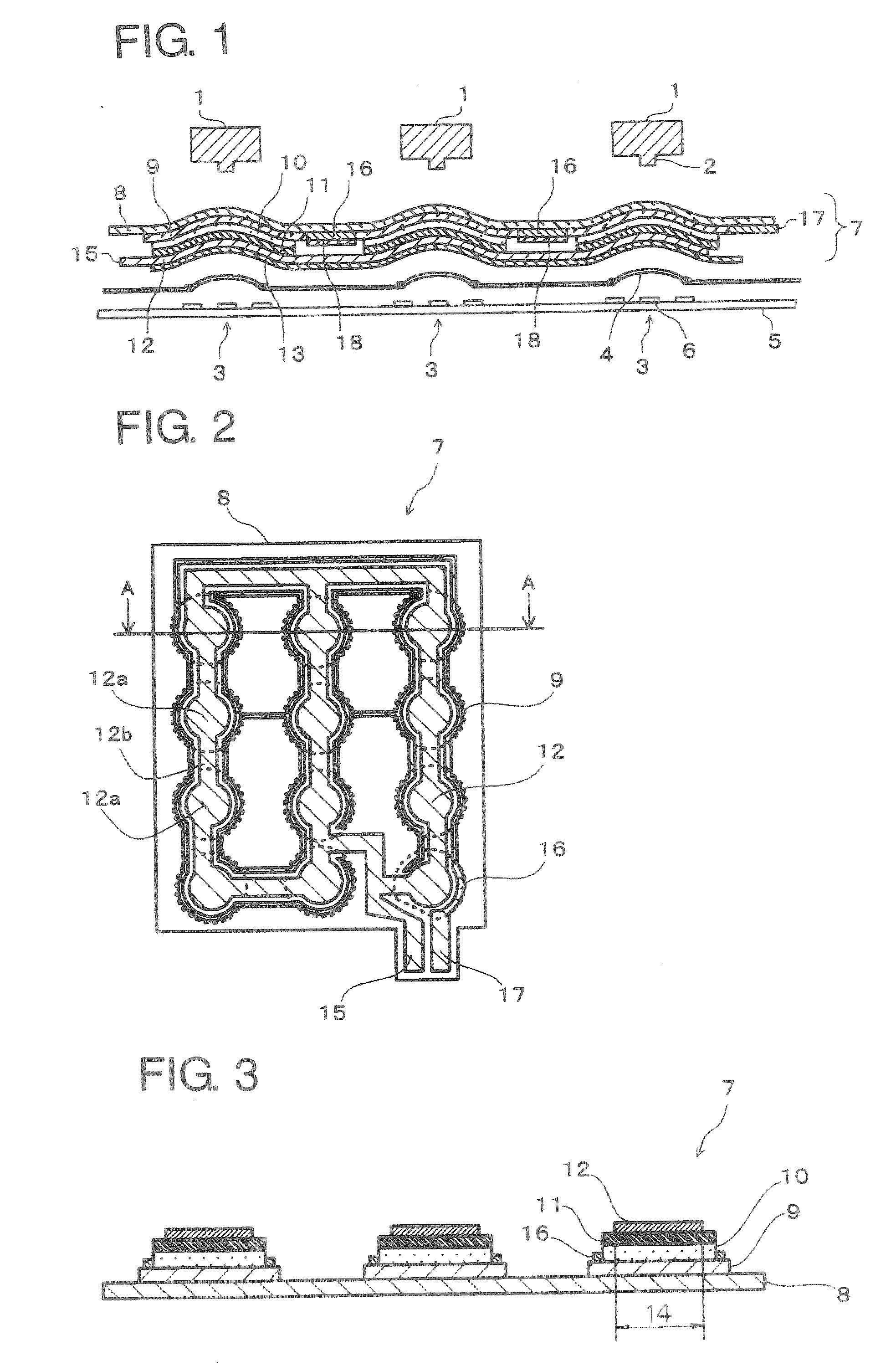
A switch illuminating EL sheet (7) has a structure such that a transparent protection film (8), a transparent electrode layer (9), a light emitting layer (10), a dielectric layer (11) and a back electrode layer (12) are layered in order from a light emitting face side. The transparent protection film (8) has a thickness of 10 μm to 60 μm. Further, the transparent electrode layer (9) is constituted of a conductive polymer. Such an EL sheet (7) can suppress wire breakage or failure to light due to keystroke stress or the like without impairing reliability and clicking feeling of a key switch. The EL sheet (7) is arranged, for example, between a key top (1) and a switch mechanism portion (2) as a light source for illuminating the key top portion (1).

Description

TECHNICAL FIELD [0001] The present invention relates to a switch illuminating EL sheet used for illumination of a switch such as a key switch, and an illuminated switch and an electronic apparatus using the same. BACKGROUND ART [0002] In a mobile communication apparatus such as a cellular phone, PDA and the like, a CD player, an MD player, a small tape recorder, a remote control switch, or a small electric electronic apparatus mounted on a motor vehicle, illumination of a switch portion (such as a key top portion) of a key switch is performed. As a light source for such an illuminated switch in which a key top portion of a key switch is illuminated, generally a light bulb or an LED is adopted. [0003] For the illuminated switch a structure having a key top, a switch mechanism portion such as a metal dome switch, a subs-rate and an LED as a light source is generally used. Incidentally, for mobile communication apparatuses such as a cellular phone and PDA, there is a strong demand to m...

Claims


Application Information

Patent Timeline
IPC IPC(8): F21V9/16H01H13/02H01H13/70H01H13/83H05B33/04H05B33/14H05B33/28
CPCH01H13/83H01H2209/002H01H2209/016H01H2209/06H05B33/14H01H2219/018H01H2219/046H01H2219/052H01H2209/082H05B33/04
Inventor NAKAMURA, MITSUOSHIGENOBU, KOJIYAMADA, SHUNICHI
Owner TOSHIBA MATERIALS CO LTD
Learn More