Oxygen absorbent molding and organic electroluminescent element

a technology of organic electroluminescent elements and absorbents, which is applied in the field of oxygen absorbents, can solve the problems of short continuous operation life of elements, short light emitting life of elements, and degradation of luminescent properties, and achieves the effects of reducing the risk of accidental ingestion, reducing the risk of powder leakage, and superior oxygen absorption capability and mechanical strength

Inactive Publication Date: 2007-08-09
MITSUBISHI GAS CHEM CO INC
View PDF2 Cites 25 Cited by
  • Summary
  • Abstract
  • Description
  • Claims
  • Application Information

AI Technical Summary

Benefits of technology

[0052] The invention provides an oxygen absorbent molding having superior oxygen-absorbing capability and mechanical strength. Specifically speaking, it is possible to provide an oxygen absorbent molding that involves a low risk of accidental ingestion and no risk of powder leakage, and exhibits superior oxygen-absorbing capability compared to that of a conventional oxygen absorbing sheet. In particular, the oxygen absorbent molding according to the invention exhibits an oxygen absorption speed equivalent to that of the oxygen absorber in a small sachet filled with the oxygen absorbent powder, and higher than that of a oxygen absorbing sheet made of an oxygen absorbent sheet. It is also possible to provide an oxygen absorbent molding that can be formed into any shape and having superior mechanical strength.
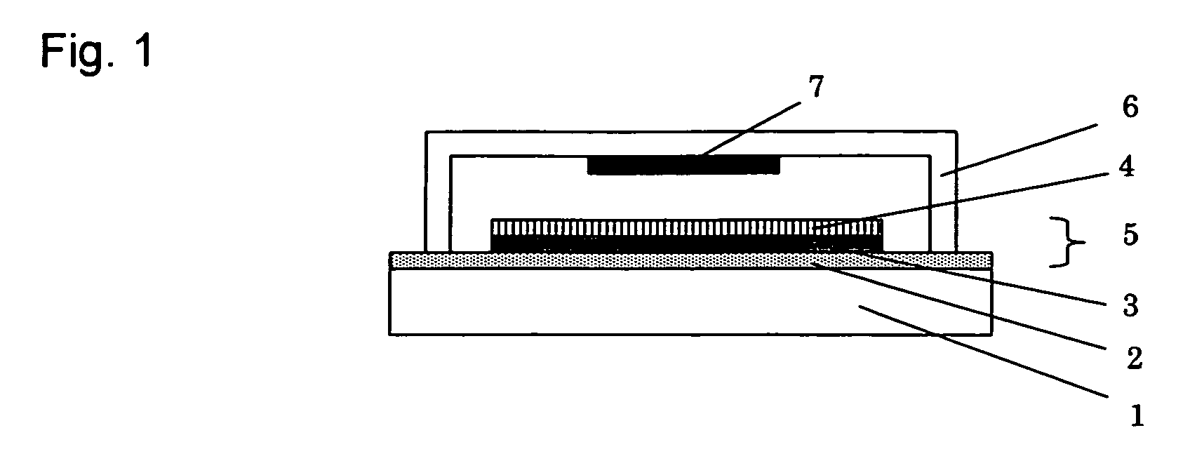
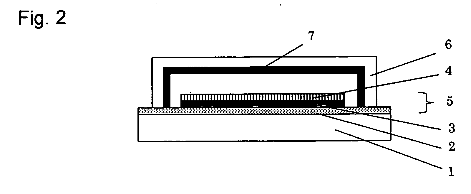
[0053] Since the inside of the organic electroluminescent element can be always maintained in a dry and anoxic state by using the oxygen absorbent molding or the gas absorbent molding according to the invention, the life of the luminescent element can be improved. In particular, the gas absorbent molding according to the invention can be easily secured inside the organic electroluminescent element, promptly remove moisture existing within or entering the sealed organic electroluminescent element, and also promptly remove oxygen existing within or entering the organic electroluminescent element in a dry atmosphere. Accordingly, the life of the organic electroluminescent element can be extended. The organic electroluminescent element with a long element life is provided by combining the gas absorbent molding according to the invention and the luminescent structure.

Problems solved by technology

However, the biggest problem of the organic electroluminescent element for practical use is that the element's light emitting life is short; particularly, the element's continuous operation life is short.
The reason for the element's short life is considered to be that a slight amount of moisture and oxygen existing inside the element causes deterioration of electrode materials and organic compounds, thereby generating non-luminous parts (or dark spots) and resulting in degradation of the luminescent property.
However, oxygen existing within the element and entering the element from outside cannot be removed completely by these methods.
However, the oxygen adsorbents used in the above-described methods are substances such as activated carbon, silica gel, and molecular sieves that can adsorb oxygen in a manner competing with moisture, or alkali earth metal compounds, and do not have sufficient oxygen-absorbing capability.
However, these oxygen absorbents have problems in that they do not exhibit sufficient oxygen-absorbing capability if moisture does not coexist; and the oxygen-absorbing speed of these oxygen absorbents is very slow under the dry conditions that are necessary inside the organic electroluminescent element.
Therefore, the disadvantage of these oxygen absorbers is that their oxygen absorption capacity (the maximum oxygen absorption amount per unit weight or unit volume) is smaller and their oxygen absorption speed is slower than the oxygen absorbers in small sachets.
However, it was found that this oxygen absorbent molding has a problem in that it may break upon a strong impact.

Method used


Image

  • Oxygen absorbent molding and organic electroluminescent element
  • Oxygen absorbent molding and organic electroluminescent element
  • Oxygen absorbent molding and organic electroluminescent element

Examples


example 1

[0105] Oxygen absorbent powder was obtained by mixing 1000 g of reduced iron powder (mean diameter: 50 μm) and 50 g of 50 wt % calcium chloride in aqueous solution, drying the obtained mixture, and then screening the dried mixture to remove coarse particles.

[0106] Subsequently, 3.0 g of this oxygen absorbent powder was mixed with 0.158 g of PTFE powder (product name “6-J”; manufactured by DU PONT-MITSUI FLUOROCHEMICALS COMPANY, LTD; melting point of 332 degrees C.) (weight ratio of the oxygen absorbent powder:PTFE=95:5), and the mixture was mixed well at room temperature (about 28 degrees C.), using a mortar. The obtained agglomerate was rolled into a sheet-form oxygen absorbent molding A (thickness: 300 μm). FIG. 4 shows a scanning electron microscope (SEM) photograph of the oxygen absorbent molding A. The oxygen absorbent molding A is a structure in which the oxygen absorbent powder containing the reduced iron powder as its principal oxidizing component is bound together and unit...

example 2

[0111] Oxygen absorbent powder was obtained by dissolving 60 g of FeSO4.7H2O and 100 g of Na2CO3.10H2O in 45 wt % sodium L-ascorbate in aqueous solution, and impregnating 600 g of activated carbon powder (mean diameter: 10 μm) with the full amount of the above-obtained solution.

[0112] Subsequently, 0.85 g of the oxygen absorbent powder obtained above was mixed with 0.15 g of PTFE powder (product name “POLYFLON F-104”; manufactured by DAIKIN INDUSTRIES, LTD.) (weight ratio of the oxygen absorbent powder:PTFE=85:15), and the mixture was mixed well at room temperature, using a mortar. The obtained agglomerate was rolled into sheet-form oxygen absorbent molding D (thickness: 300 μm). An area of size 3 cm×6 cm (0.63 g) of the oxygen absorbent molding D was cut out. The cutout piece of the oxygen absorbent molding D was put, together with 800 ml of air, in an oxygen-impermeable bag, which was then sealed. The oxygen absorbent molding D in the oxygen-impermeable bag was stored in a 60% RH...

example 3

[0113] In this example, 0.9 g of the oxygen absorbent powder prepared in the same manner as in Example 2 was mixed with 0.1 g of the same PTFE powder as used in Example 2 (weight ratio of the oxygen absorbent powder:PTFE=90:10), and the mixture was well mixed at room temperature (about 25 degrees C.), using a mortar. Then, a tablet machine (diameter: 12 mm) was filled with 0.82 g of the obtained agglomerate and compression molding was performed at a pressure of 1 t / cm2, thereby obtaining tablet-form oxygen absorbent molding E (each tablet being 12 mm in diameter and 7.2 mm high). This oxygen absorbent molding E was put, together with 800 ml of air, in an oxygen-impermeable bag, which was then sealed. The oxygen absorbent molding E in the oxygen-impermeable bag was stored in a 60% RH atmosphere at a temperature of 25 degrees C. The initial oxygen absorption speed and the maximum oxygen absorption amount on an oxygen absorbent powder weight basis were measured in the same manner as in...


PUM

PropertyMeasurementUnit
specific surface areaaaaaaaaaaa
diameteraaaaaaaaaa
diameteraaaaaaaaaa

Abstract

An oxygen absorbent molding or a gas absorbent molding is provided. The oxygen absorbent molding is made of oxygen absorbent powder and a binder, and is characterized in that the binder is a fibrous resin. Fluororesin can be used as the fibrous resin. This oxygen absorbent molding has excellent oxygen-absorbing capability and mechanical strength and is suited for extending the life of an organic electroluminescent element.

Description

TECHNICAL FIELD [0001] The present invention relates to an oxygen absorbent. [0002] This invention also relates to a gas absorbent molding and an organic electroluminescent element using the gas absorbent molding. [0003] The term “oxygen absorbent” used in this specification means an oxygen-absorbing composition that is solid or liquid at ordinary temperatures and contains an oxygen-absorbing component capable of absorbing oxygen by means of a chemical reaction. The term “oxygen absorbent powder” means an oxygen-absorbing composition in powder form that contains an oxygen-absorbing component in a solid state at ordinary temperatures, and a powder-form oxygen-absorbing composition made by having carrier powder carry or be impregnated with an oxygen-absorbing composition which contains an oxygen-absorbing component in a solid or liquid state at ordinary temperatures. The term “oxygen absorber” means a package of the oxygen absorbent. The term “binder” means a substance added to bind p...

Claims


Application Information

Patent Timeline
Patent Type & Authority Applications(United States)
IPC IPC(8): B32B19/00B01J20/02B01J20/22B01J20/26B01J20/28H01L51/52H05B33/04H05B33/14
CPCB01J20/02H05B33/04B01J20/041B01J20/046B01J20/22B01J20/26B01J20/28026B01J20/28028B01J20/2803B01J20/28042B01J20/28057B01J20/3007B29B11/10H01L51/5237B01J20/0229B01J20/06B01J20/10B01J20/24B01J20/261B01J20/262B01J20/264B01J20/3028B01J20/0288B01J20/103B29C49/071B29C2949/0715H10K50/846H10K50/841B29B9/08B29B11/06B29B11/12B29B11/14B29C70/00H05B33/14H10K50/84
Inventor YOKOSE, EMIKOYOKOYAMA, JUNSUMITANI, MAKOTO
Owner MITSUBISHI GAS CHEM CO INC
Why Eureka
Try Eureka