Coating system and coating method

a coating system and coating technology, applied in the field of coating systems, can solve the problems of long duration of the evacuating process, inadequate adhesion of chemical structures, and inacceptable poor quality of coatings, and achieve the effect of improving the productivity of coating systems

Inactive Publication Date: 2007-08-16
SIEMENS AG
View PDF7 Cites 4 Cited by
  • Summary
  • Abstract
  • Description
  • Claims
  • Application Information

AI Technical Summary

Benefits of technology

[0004] Starting from the problems and disadvantages of the prior art, it has been made the object of the invention to improve the productivity of coating systems, especially low pressure plasma coating systems for coating gas turbine blades, without having to accept losses in the quality of the coating.
[0006] A temperature control of the treatment chamber, according to the invention, at a temperature of between 45° C. and 75° C., takes place preferably by means of heat exchangers on the walls of the chamber, which exchange the heat between the chamber walls and a heat transfer fluid, for example water. In the previous prior art, a temperature control of the chamber takes place at a temperature of about 20° C. The increase of the chamber temperature or the temperature of the chamber walls, as the case may be, to 45° C. to 75° C., preferably to 55° C. to 65° C., according to the invention, which produced the best results with regard to the treatment duration and the coating quality, has the great advantage that the desired vacuum can be achieved quicker, and, on account of the high quality of the vacuum, a reduction of the absorption of components of the air from the environment can be very much reduced within the scope of the coating process. Consequently, the quality of the coating is increased, with a simultaneous reduction of the treatment time per workpiece. These positive effects are attributable to the higher temperature of the chamber or the chamber walls, as the case may be, very much reducing the condensation of components of the constantly moist air on the chamber walls or on the contaminants there, as the case may be. If the duration of the evacuation is maintained, a lower pressure can be achieved. On account of the lower volume of condensates in the region of the chamber walls, the negative pressure or the vacuum, as the case may be, is also sustainably stable, since the volume of subsequently evaporating condensates is much reduced on account of the increased temperature.
[0007] A further advantage of the increased chamber temperature or chamber wall temperature, as the case may be, results from the workpiece being preheated for the most part to about 900° C. for the purpose of coating, and this temperature should be maintained even during the coating process in the interests of a high coating quality. The increased chamber wall temperature, compared to the prior art, is instrumental in even large workpieces as far as possible maintaining their increased temperature during the coating process. This effect is to be attributed basically to the altered heat balance first of all as a result of heat radiation into the evacuated chambers. As a result of the application of the method according to the invention or the implementation of a coating system according to the invention, as the case may be, the productivity is increased by almost 10%.
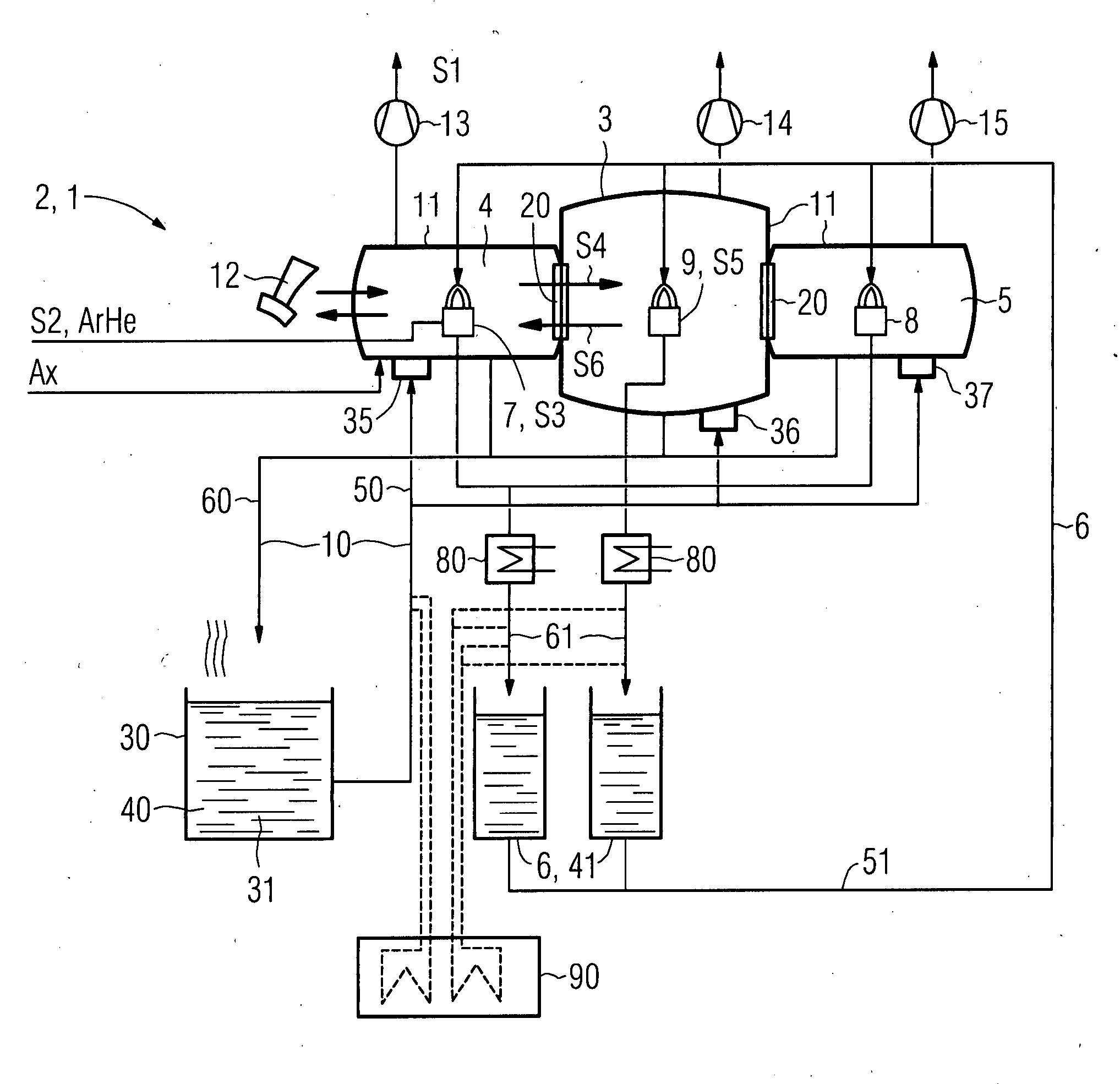
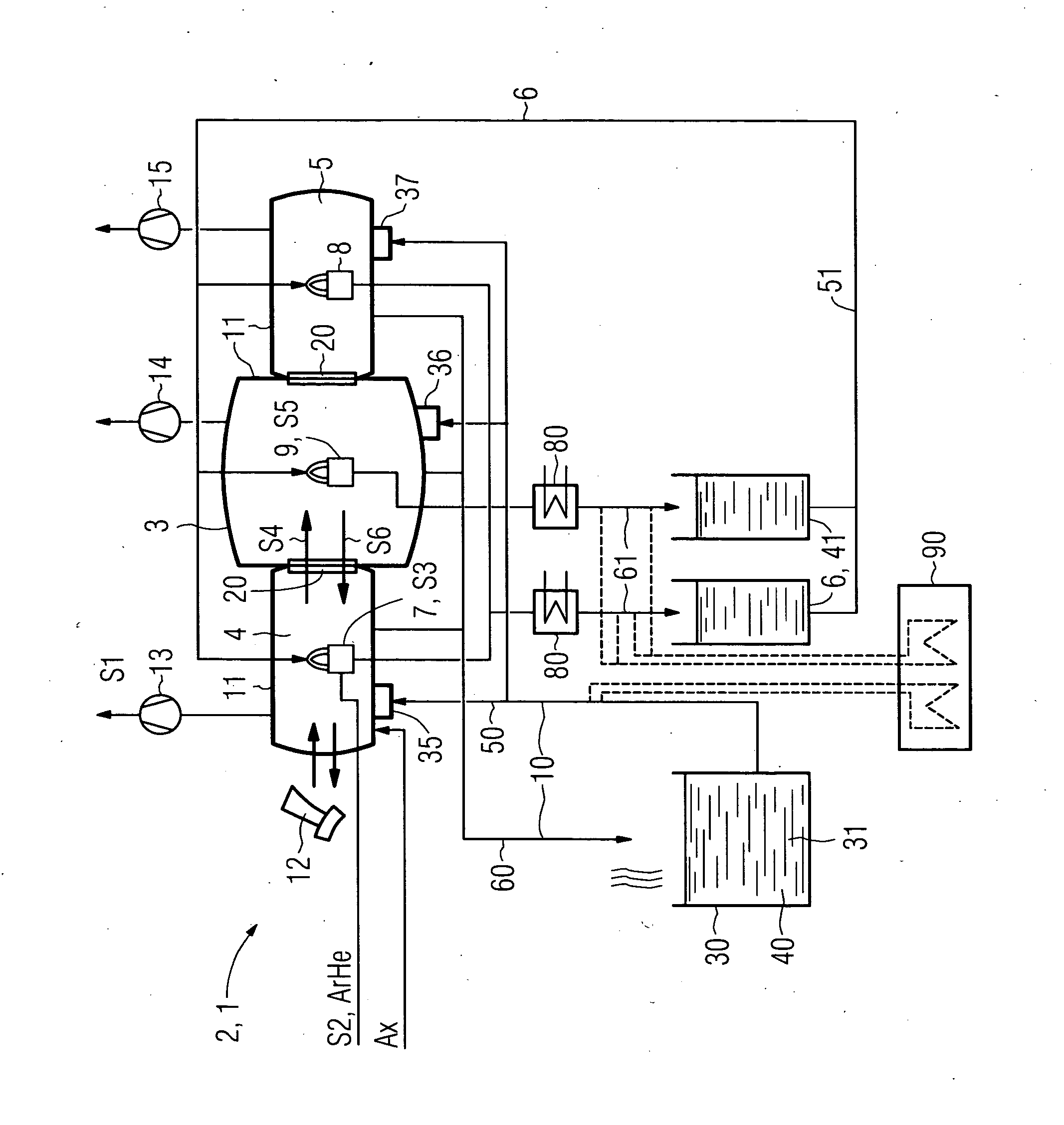
[0008] The coating system expediently has a second heat exchanger in addition to a first heat exchanger in the region of the chamber walls, which regulates the inlet temperature for the first heat exchanger at 55° C. to 65° C. In the interests of a high throughput of workpieces which are to be coated, it is expedient if the coating system additionally has at least one, preferably two, antechambers in addition to the actual treatment chamber, in which antechambers the workpieces are heated to a temperature of preferably 900° C. which is expedient for the coating. In addition to a temperature control of the antechamber at a temperature of 45° C. to 75° C., it is sensible if the antechambers also experience such a temperature control. In order to carry out the actual coating in a space which is protected as far as possible, it is advantageous if the treatment chamber, in which the coating takes place, is separable from the antechambers in each case by means of a closable partition. Such a lock also enables the maintaining of a high vacuum quality, especially in the treatment chamber. Within the scope of the necessary opening of the partition during the transfer of a workpiece from an antechamber into the treatment chamber, and during the pressure equalization between the treatment chamber and the antechamber which is associated with it, the antechamber can already be evacuated to the level of the treatment chamber so that the treatment chamber, basically without interruption, has the necessary negative pressure for the coating.

Problems solved by technology

The coating technique is confronted in this connection with a constant challenge by means of increasing demands on the service life of the coating under high load.
A high-powered pump system requires about 90 seconds for evacuation of a chamber to the desired negative pressure in the case of component parts in the size of a gas turbine blade, for example, which duration has a direct and significant influence on the manufacturing costs of the end product.
If this time period is curtailed, it leads to an unacceptably poor quality of the coating, since a too intense absorption of air from the environment during the coating leads either to inadequately adhering chemical structures or to an unwanted chemical change of the coating material.
A reason for the long duration of the evacuating process is to be seen inter alia in the unavoidable contamination of the walls of the treatment chambers or antechambers, as the case may be, of such systems.
The contaminant layers absorb especially condensates from the moist environmental air in large volumes, which, during the evacuating, evaporate over a long period of time and persistently degrade the quality of the vacuum.

Method used


Image

  • Coating system and coating method
  • Coating system and coating method

Examples


Embodiment Construction

[0013]FIG. 1 shows a coating system 1 according to the invention, which is formed as a low pressure plasma coating system 2, and, as essential component parts, has a treatment chamber 3 and two antechambers 4, 5, and also a cooling circuit 6 for cooling of the burners 7, 8 and a coating tool 9, and also a temperature control circuit 10 for temperature control of the antechambers 4, 5 and the treatment chamber 3.

[0014] The coating system 1 serves for the coating of workpieces 12, which in a first step S1 are introduced into a first antechamber 4 which is evacuated to a vacuum of 0.1 mbar by means of a first pump 13. Then, the first antechamber 4 is flooded with a protective gas, argon, at a pressure of 30 mbar (second step S2). By means of the first burner 7, the workpiece 12 is heated to a temperature of 900° C. by combustion of an argon-helium mixture (third step S3). In a fourth step S4, a transporting of the workpiece 12 into the treatment chamber 3 takes place, wherein first of...


PUM

PropertyMeasurementUnit
temperatureaaaaaaaaaa

Abstract

The invention relates to a coating system, especially a low pressure plasma coating system, with at least one treatment chamber and a coating tool, especially a plasma spraying device, wherein at least one pump is provided for evacuation of the treatment chamber, which treatment chamber is formed to be temperature controllable. In addition there is a coating method for low pressure plasma coating with a temperature controlled and evacuated treatment chamber, in which a workpiece is coated by means of at least one coating tool. For acceleration of the coating process, especially the evacuating of the treatment chamber, it is proposed that at least the walls of the treatment chamber and / or the inside of the treatment chamber are temperature controlled at a temperature between 45° C. and 75° C.

Description

CROSS REFERENCE TO RELATED APPLICATIONS [0001] This application claims the benefits of European Patent application No. 06000641.8 filed Jan. 12, 2006. All of the applications are incorporated by reference herein in their entirety. FIELD OF INVENTION [0002] The invention relates to a coating system, especially a low pressure plasma coating system, with at least one treatment chamber and a coating tool, especially a plasma spraying device, wherein at least one pump is provided for evacuation of the treatment chamber, which treatment chamber is formed to be temperature controllable. In addition, a coating method with a temperature controlled and evacuated treatment chamber, in which a workpiece is coated by means of at least one coating tool, is the subject of the invention. BACKGROUND OF THE INVENTION [0003] Coatings are frequently used to improve the superficial mechanical or chemical properties of a workpiece according to the application purpose. An improvement in this case can lie ...

Claims


Application Information

Patent Timeline
Patent Type & Authority Applications(United States)
IPC IPC(8): C23C14/00B05C5/00B05B5/025
CPCC23C4/127C23C4/02C23C4/134
Inventor LADRU, FRANCIS-JURJENREICH, GERHARDRIEMANN, MICHAELSTADELMAIER, FALK
Owner SIEMENS AG
Why Eureka
Try Eureka