High-efficiency solar cell with insulated vias

a solar cell and high-efficiency technology, applied in the field of optoelectronic devices, can solve the problems of premature failure of solder joints, incompatibility of solder and silicon wafer materials, and individual optoelectronic devices producing only a relatively small voltage, so as to minimize the amount of material deposited.

Inactive Publication Date: 2007-08-16
AERIS CAPITAL SUSTAINABLE IP
View PDF2 Cites 120 Cited by
  • Summary
  • Abstract
  • Description
  • Claims
  • Application Information

AI Technical Summary

Benefits of technology

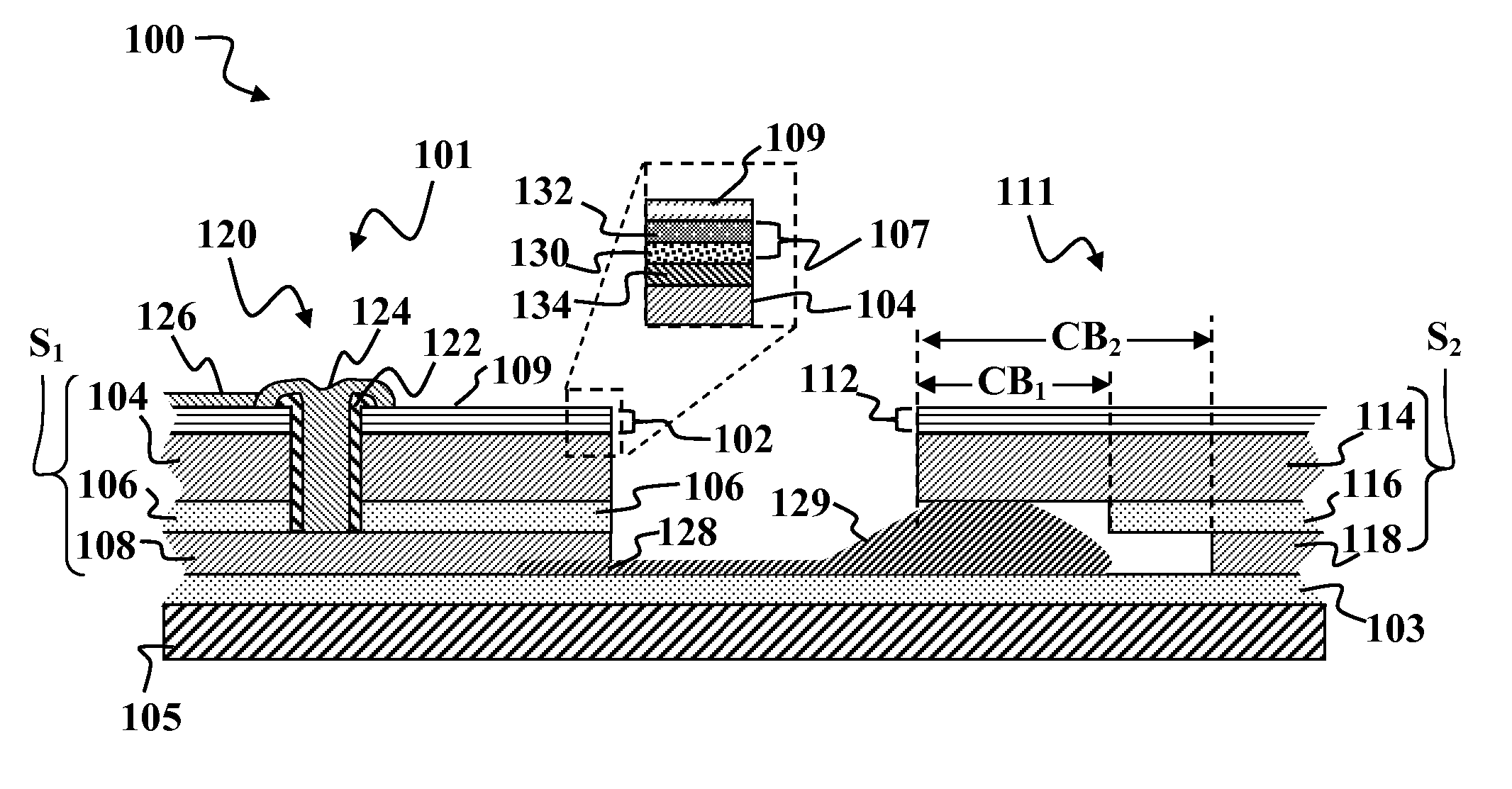
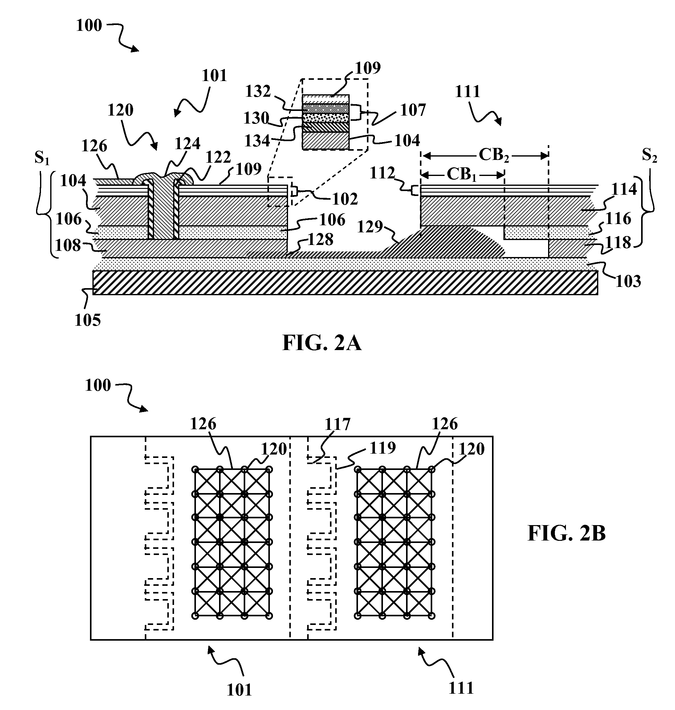
[0018] It should be understood that the coating step may be comprised of using a source that sprays insulating material from an underside of the solar cell to avoid substantially covering the transparent conductor with insulating material. Coating may also be comprised of spraying an insulating material from an underside of the solar cell to minimize the amount of material deposited on the transparent conductor without using a mask on the transparent conductor. Coating may be comprised of spraying an insulating material from a top side of the solar cell

Problems solved by technology

Currently, there are a number of technical challenges to attaining this goal.
A further problem associated with existing solar fabrication techniques arises from the fact that individual optoelectronic devices produce only a relatively small voltage.
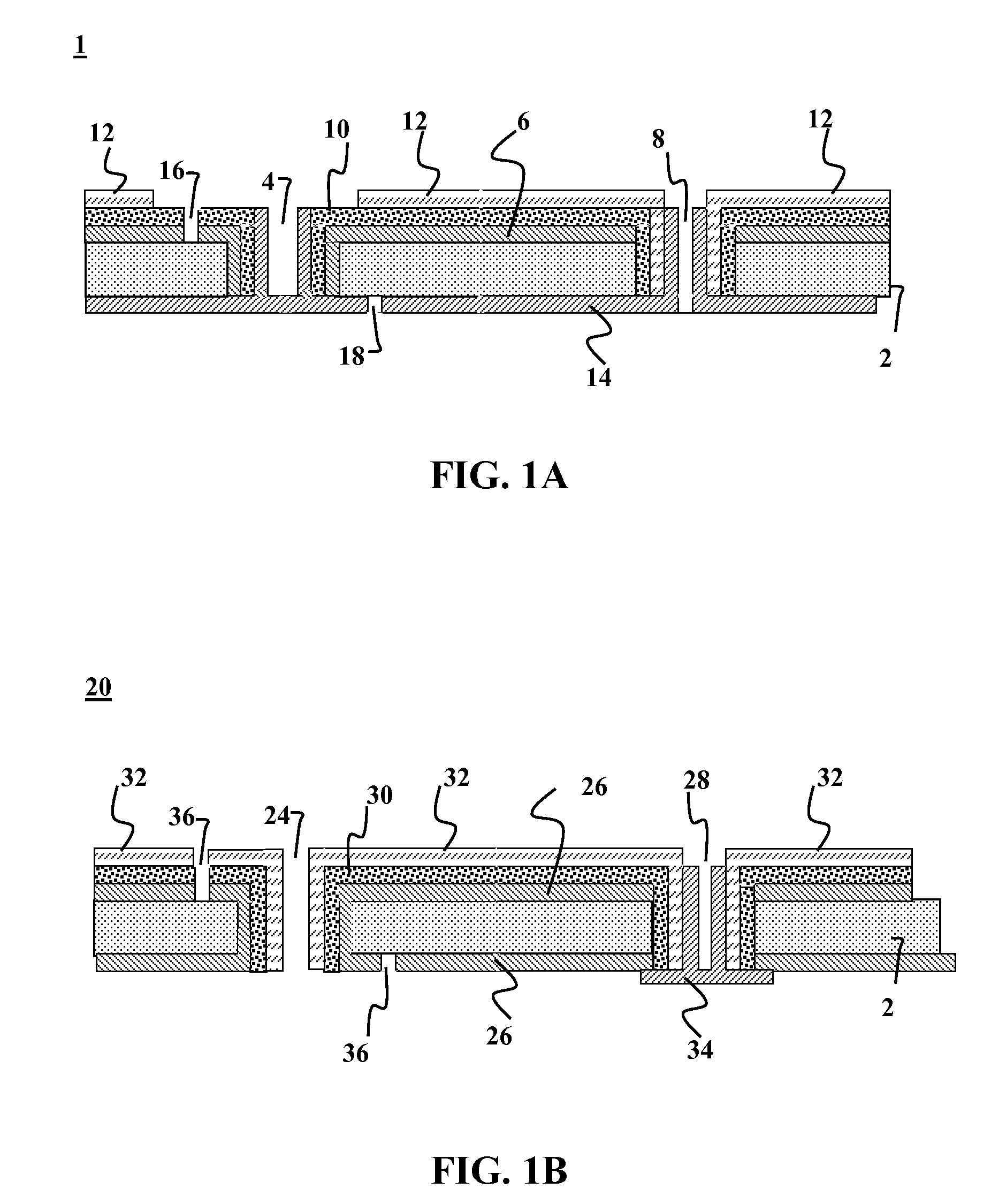
Unfortunately the solder and silicon wafer materials were not compatible.
The differing rates of thermal expansion between silicon and solder and the rigidity of the wafers caused premature failure of the solder joints with temperature cycling.
A further problem associated with series interconnection of optoelectronic devices arises from the high electrical resistivity associated with the TCO used in the transparent electrode.
However, the fingers and busses produce shadowing that reduces the overall efficiency of the cell.
Consequently, a large number of small cells must be connected together, which requires a large number of interconnects and more space between cells.
Arrays of large numbers of small cells are relatively difficult and expensive to manufacture.
Further, with flexible solar modules, shingling is also disadvantageous in that the interconnection of a large number of shingles is relatively complex, time-consuming and labor-intensive, and therefore costly during the module installation process.
Although this technique does redu

Method used


Image

  • High-efficiency solar cell with insulated vias
  • High-efficiency solar cell with insulated vias
  • High-efficiency solar cell with insulated vias

Examples


Embodiment Construction

[0036] It is to be understood that both the foregoing general description and the following detailed description are exemplary and explanatory only and are not restrictive of the invention, as claimed. It may be noted that, as used in the specification and the appended claims, the singular forms “a”, “an” and “the” include plural referents unless the context clearly dictates otherwise. Thus, for example, reference to “a material” may include mixtures of materials, reference to “a compound” may include multiple compounds, and the like. References cited herein are hereby incorporated by reference in their entirety, except to the extent that they conflict with teachings explicitly set forth in this specification.

[0037] In this specification and in the claims which follow, reference will be made to a number of terms which shall be defined to have the following meanings:

[0038]“Optional” or “optionally” means that the subsequently described circumstance may or may not occur, so that the...


PUM


Abstract

Methods and devices are provided for high-efficiency solar cells. In one embodiment, the device comprises of a solar cell having a high efficiency backside electrode configuration, wherein the solar cell comprises of: at least one transparent conductor, a photovoltaic layer, at least one bottom electrode, and at least one backside electrode. The device may include a plurality of electrical conduction fingers mounted to the transparent conductor in the solar cell. The device may include a plurality of filled vias coupled to the electrical conduction fingers, wherein the vias extend through the transparent conductor, the photovoltaic layer, and the bottom electrode, wherein the vias have a conductive core that conducts charge from the transparent conductor to the backside electrode. The via insulating layer may separate the conductive core in each via from the bottom electrode, wherein the insulating layer may be formed by a variety of techniques such as but not limited to aerosol coating of the via.

Description

CROSS-REFERENCE TO RELATED APPLICATION [0001] This application is a continuation-in-part of commonly-assigned, co-pending U.S. patent application Ser. No. 11 / 207,157 entitled “OPTOELECTRONIC ARCHITECTURE HAVING COMPOUND CONDUCTING SUBSTRATE” filed Aug. 16,2005 which is a continuation-in-part of commonly-assigned, co-pending U.S. patent application Ser. No. 11 / 039,053 entitled “SERIES INTERCONNECTED OPTOELECTRONIC DEVICE MODULE ASSEMBLY” filed Jan. 20, 2005. This application also claims the benefit of priority to U.S. Provisional Patent Application Ser. No. 60 / 781,165 entitled HIGH-EFFICIENCY SOLAR CELL WITH INSULATED VIAS filed on Mar. 10, 2006. The entire disclosures of the above applications are fully incorporated herein by reference for all purposes.FIELD OF THE INVENTION [0002] This invention relates to optoelectronic devices and more particularly to mass-manufacture of optoelectronic devices such as solar cells. BACKGROUND OF THE INVENTION [0003] Optoelectronic devices can conv...

Claims


Application Information

Patent Timeline
IPC IPC(8): H01L31/00
CPCH01L27/3204H01L31/022425H01L31/0392H01L31/0516H01L31/0749H01L31/046H01L51/5203Y02E10/541H01L31/02245H01L31/0508H01L31/0512H01L31/18H01L31/0463H01L31/03923H01L31/03925H10K59/86H10K50/805
Inventor LOCHUN, DARRENSHEATS, JAMES R.MILLER, GREGORY A.
Owner AERIS CAPITAL SUSTAINABLE IP
Why Eureka
Try Eureka