System for Treating Mitral Valve Regurgitation

Inactive Publication Date: 2007-08-30
MEDTRONIC VASCULAR INC
View PDF69 Cites 255 Cited by
  • Summary
  • Abstract
  • Description
  • Claims
  • Application Information

AI Technical Summary

Benefits of technology

[0023] Another aspect of the present invention is a method of treating mitral valve regurgitation by affecting a mitral valve annulus. A first wall of a chamber of a heart is pierced by a puncture catheter. A distal anchor is engaged with a second wall of the heart chamber. A proximal anchor is engaged with the first wall of the heart chamber. A tension member affixed to and linking the proximal and distal anchors, applies a constant tension force to reduce the

Problems solved by technology

This results in reduced ejection volume from the left ventricle, causing the left ventricle to compensate with a larger stroke volume.
The increased workload eventually results in dilation and hypertrophy of the left ventricle, further enlarging and distorting the shape of the mitral valve.
If left untreated, the condition may result in cardiac insufficiency, ventricular failure, and death.
This is a complex, invasive surgical procedure with the potential for many complications and a long recovery period.
Rigid annuloplasty rings have the disadvantage of causing the mitral valve annulus to be rigid and unable to flex in response to the contractions of the ventricle, thus inhibiting the normal movement of the mitral valve that is required for it to function optimally.
This eventually leads to scar tissue formation and loss of flexibility and function of the mitral valve.
Similarly, combination rings must generally be sutured in place and also cause scar tissue formation and loss of mitral valve flexibility and function.
However, the coronary sinus in a particular individual may not wrap around the heart far enough to allow effective e

Method used


Image

  • System for Treating Mitral Valve Regurgitation
  • System for Treating Mitral Valve Regurgitation
  • System for Treating Mitral Valve Regurgitation

Examples


Embodiment Construction

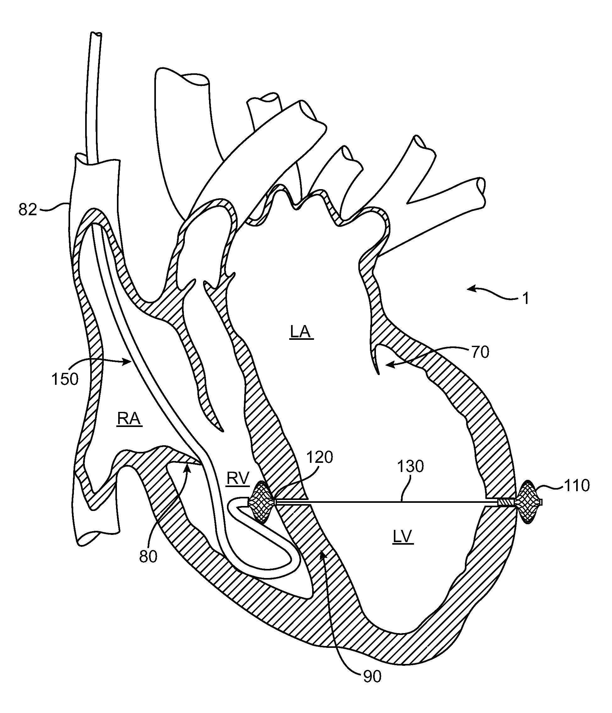
[0040] The invention will now be described in detail below by referring to the attached drawings, where like numbers refer to like structures. The present invention discloses a system for treating regurgitation in heart valves. The system is shown and described herein as it would be used to treat regurgitation of the mitral valve. The system includes catheters for navigating through the vasculature to chambers of a heart. The catheters can be used for delivering devices for treating heart valve regurgitation. The system also includes catheters for puncturing the wall of a heart chamber.

[0041] The catheter is delivered to the heart by passing it through the venous system. This may be accomplished by inserting the catheters into either the jugular vein or the subclavian vein and passing it through the superior vena cava and into the right atrium. Alternatively, the catheter may be inserted into the femoral vein and passed through the common iliac vein and the inferior vena cava into ...


PUM


Abstract

A system for treating mitral valve regurgitation comprising at least delivery catheters, puncture catheters, and tensioning devices. The devices include tension members linking a proximal anchor and distal anchor that can be constructed from a tubular braded material and have internal reinforcing members. In some embodiments, the anchors and tension members may flex in response to a heart beat. The system can also include temporary anchors so a clinician can review and adjust the vector of the tension member. Delivery catheters can also include temporary anchors to secure the catheter in position. When positioned across the left ventricle of a heart, the device can reduce the lateral distance between the walls of the ventricle and thus allow better coaption of the mitral valve leaflets thereby reducing heart valve regurgitation.

Description

RELATED APPLICATIONS [0001] This application claims priority under 35 U.S.C. §119(e) from U.S. Provisional Application No. 60 / 743,349, filed February 24.TECHNICAL FIELD [0002] This invention relates generally to medical devices and particularly to a system and method for treating mitral valve regurgitation by reducing the lateral space between the ventricular septum and the free wall of the left ventricle. BACKGROUND OF THE INVENTION [0003] The heart is a four-chambered pump that moves blood efficiently through the vascular system. Blood enters the heart through the vena cava and flows into the right atrium. From the right atrium, blood flows through the tricuspid valve and into the right ventricle, which then contracts and forces blood through the pulmonic valve and into the lungs. Oxygenated blood returns from the lungs and enters the heart through the left atrium and passes through the bicuspid mitral valve into the left ventricle. The left ventricle contracts and pumps blood thr...

Claims


Application Information

Patent Timeline
IPC IPC(8): A61F2/02A61B17/34
CPCA61B17/00234A61B17/0401A61B17/0482A61B2018/00392A61B2017/00867A61B2017/06052A61B2017/00247
Inventor BLOOM, ELIOTHOUSE, MORGANRAFIEE, NASSERFINNEY, MICHAEL
Owner MEDTRONIC VASCULAR INC
Why Eureka
Try Eureka