Ink fountain roller of a web-fed press

a wedfed press and fountain roller technology, applied in printing presses, inking apparatus, printing, etc., can solve the problems of microcracks, strong abrasion and wear, and contaminants, especially calcium carbonate and kaolin, in the pores of the ink fountain roller, so as to improve the mechanical strength of metal components and reduce microcracks

Inactive Publication Date: 2007-09-13
MANROLANAD AG
View PDF8 Cites 0 Cited by
  • Summary
  • Abstract
  • Description
  • Claims
  • Application Information

AI Technical Summary

Benefits of technology

[0016] The advantages of conventional ion implantation can be transferred to large-surface, complex geometries by means of plasma immersion ion implantation, which is also referred to simply as ion implantation or vacuum plasma technology. In this regard, plasma immersion ion implantation is distinguished from thermal spray plasma coating. In plasma immersion ion implantation, the workpiece to be treated is coated in a vacuum chamber by a plasma generated by a suitable plasma source. By applying negative high-voltage pulses with a frequency of 500-2000 Hz and very short pulse rise times on the order of less than one microsecond, the more highly mobile electrons of the plasma are repelled, and the positive ions that are left behind are accelerated towards the workpiece or implanted. The acceleration voltages are in the range of 5-15 kV; this is below the acceleration voltages of conventional ion implantation, which are on the order of 30 kilovolts. Temperatures are in a range of 50-200° C., as determined by structure size, without active controls. The method finds use in the aerospace industry and in the field of medical implants due to the improvement in the mechanical strength of metal components. Another advantage of plasma immersion ion implantation is that it can be used not only for coating but also for structural modification.
[0017] The invention makes it possible to reduce microcracks with diameters in the submicron range in the surface of the ink fountain roller, so that the surface becomes smoother, and fewer contaminants can adhere to it. In addition, this plasma coating offers the specific advantage of favorable values with respect to the polar component and the disperse component of the surface energy.

Problems solved by technology

The lower the surface energy is, the more “ink-friendly” and “water-unfriendly” the surface is.
For example, contaminants, especially calcium carbonate and kaolin, can accumulate in the pores and microcracks in the surface of the ink fountain roller.
The ink transfer roller rotates at a high speed of rotation of the printing press of up to 60,000 revolutions per minute and is thus subject to strong abrasion and wear.

Method used


Image

  • Ink fountain roller of a web-fed press
  • Ink fountain roller of a web-fed press
  • Ink fountain roller of a web-fed press

Examples


Embodiment Construction

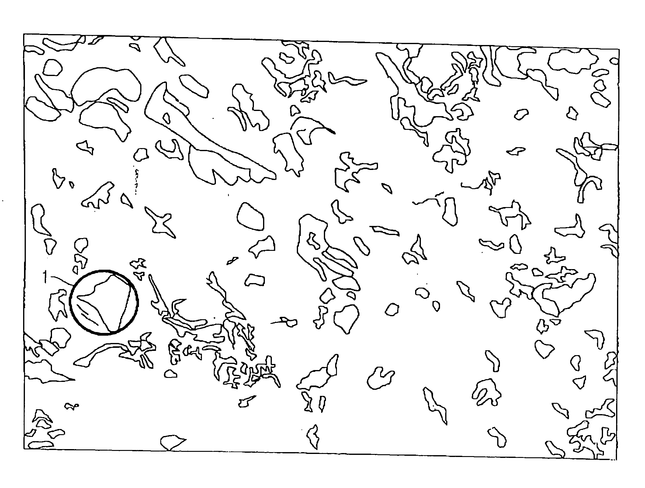
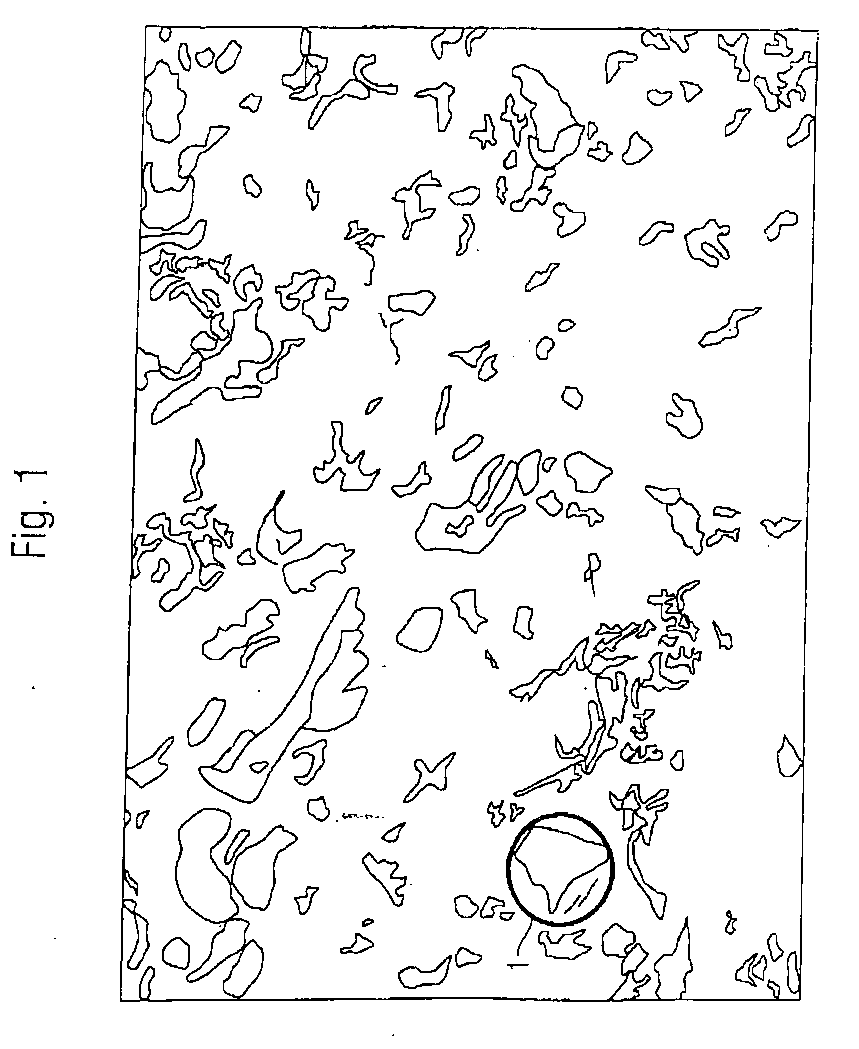
[0034]FIG. 1 is a schematic representation of a scanning electron micrograph of a ceramic coating of the surface of an ink fountain roller at a magnification of 500×. Topographic height differences were outlined in this schematic representation. The ceramic coating consists of a mixture of chromic oxide (Cr2O3) and titanium dioxide (TiO2). The section of the ceramic surface shown here corresponds approximately to a width of 250 μm and a height of 180 μm (1 μm=10−6 μm). Depressions 1 (circumscribed area) are clearly visible on this surface, and some of them have diameters of about 20 μm. The inventors realized that undesired contaminants can accumulate in these depressions. The ink fountain roller of the invention is realized with a smoother surface.

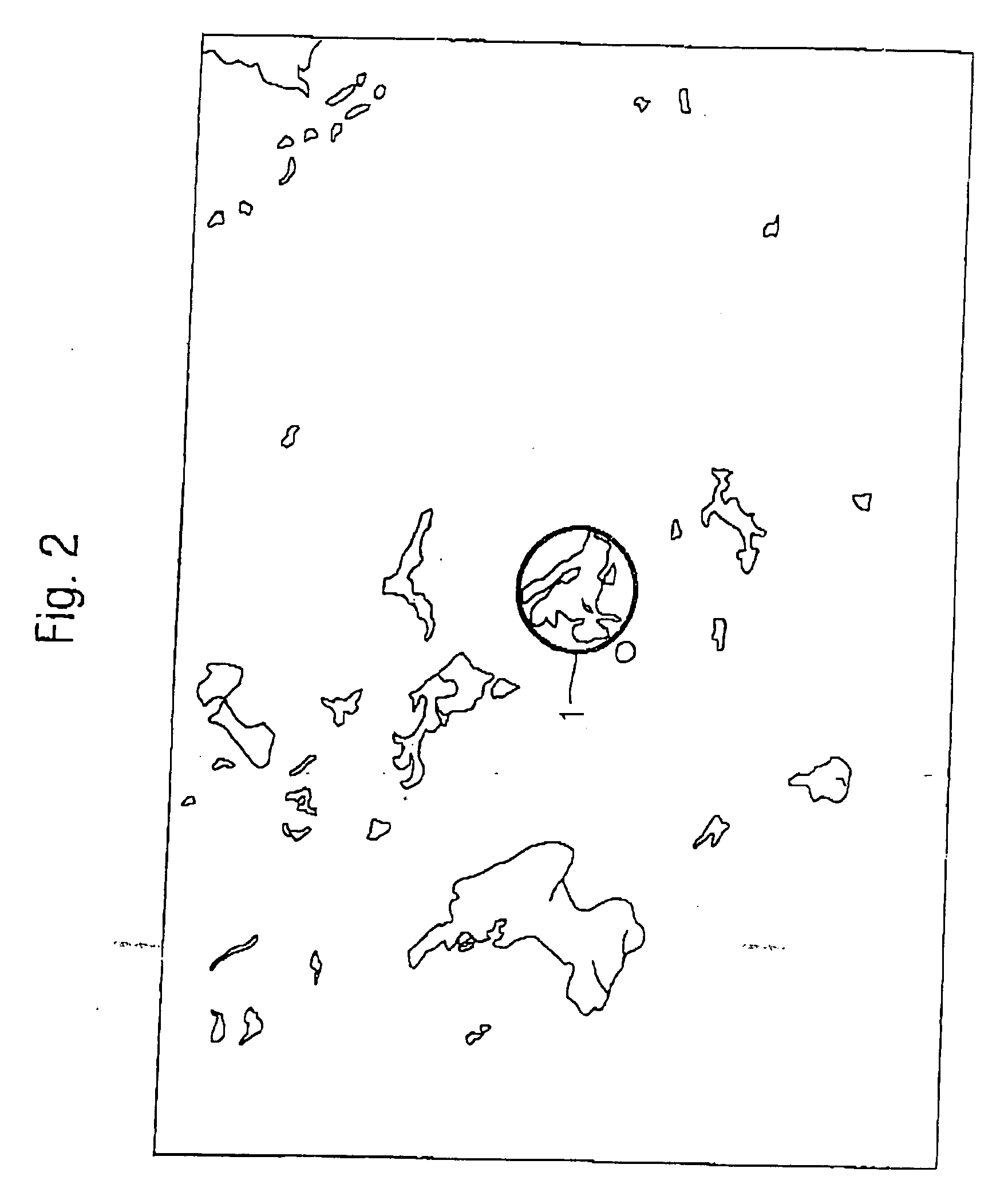
[0035]FIG. 2 is a schematic representation of a scanning electron micrograph of a metallic spray coating of the surface of an ink fountain roller at a magnification of 500×. The dimensions of the section shown here are the same as in FIG...


PUM

PropertyMeasurementUnit
total surface energyaaaaaaaaaa
surface energyaaaaaaaaaa

Abstract

An ink fountain roller has a metal core and a plasma coating that is applied by plasma immersion ion implantation. The coating has a total surface energy of 35 mN/m or less, and a polar component of less than 7 mN/m. The coating is applied in a vacuum chamber by generating a metal plasma over the core, wherein the metal has a valence of +4 or +6 and is preferably at least one of titanium, molybdenum, and zirconium. Positive ions in the plasma are accelerated toward the core by applying negative high voltage pulses (5-15 kV) with very short pulse rise times (<1 μsec) to the plasma, thereby causing positive ions in the plasma to be implanted in the core. An intermediate layer of metal or ceramic may be applied to the core prior to applying the plasma coating.

Description

BACKGROUND OF THE INVENTION [0001] 1. Field of the Invention [0002] The invention concerns an ink fountain roller of a wed-fed press with at least one inking unit from which the ink fountain roller takes up ink, wherein the ink fountain roller has a metal core. [0003] 2. Description of the Related Art [0004] Ink fountain rollers of web-fed presses receive the printing ink from a film inking unit and transfer it, usually by other ink transfer rollers, to the printing plate cylinder, which transfers the ink to a blanket cylinder and, finally, to the subject. [0005] It is essential to the printing result that the ink acceptance of the ink fountain roller is homogeneous, that the ink film on the ink fountain roller does not separate, and that the ink fountain roller does not glaze or run dry. [0006] In this regard, glazing or separation of the ink film on the ink fountain roller depends on the composition of the printing ink, the concentration of the fountain solution used in printing, ...

Claims


Application Information

Patent Timeline
Patent Type & Authority Applications(United States)
IPC IPC(8): B41F31/14
CPCB41F31/26B41N7/06B41N2207/10B41N2207/04B41N2207/02
Inventor KLARMANN, RALPHSCHULMEISTER, PETER
Owner MANROLANAD AG
Why Eureka
Try Eureka