Anisotropic Conductive Film and a Method of Manufacturing the Same

a technology of anisotropic conductive film and manufacturing method, which is applied in the manufacture of film/foil adhesives, cable/conductor connections, and coupling device connections, etc., can solve the problems of reducing reliability, difficult to ensure insulation in the film surface direction, and difficulty in making conductive particles smaller in diameter to be less than the variations in height, so as to achieve superior adhesion to the connection target, maintain connection reliability, and high reliability

Inactive Publication Date: 2007-09-13
SUMITOMO RIKO CO LTD
View PDF0 Cites 30 Cited by
  • Summary
  • Abstract
  • Description
  • Claims
  • Application Information

AI Technical Summary

Benefits of technology

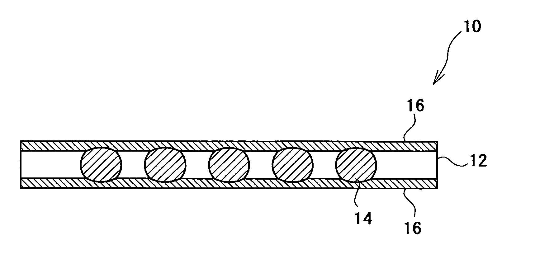
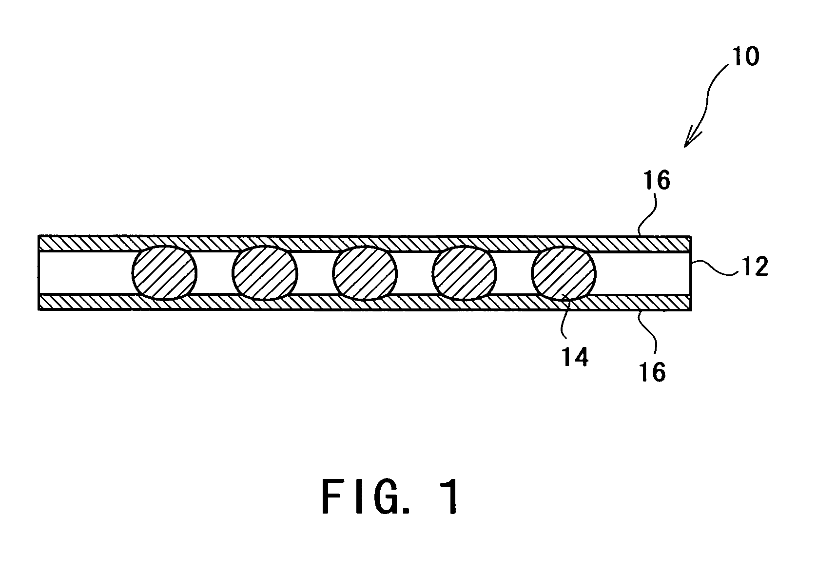
[0048] In the anisotropic conductive film according to the invention, when the adhesive layer is a prepreg of a thermosetting resin in a semi-cured state, the adhesive layer in interstices between the conductors provided to the connection targets easily flows out and adhesion to the connection targets is enhanced, so that high reliability can be ensured.
[0049] In this case, when the thermosetting resin is an epoxy resin, there is superior adhesion to the connection targets.
[0050] At the same time, in the method of manufacturing the anisotropic conductive film according to the invention, as compared to the conventional anisotropic conductive film wherein conductive particles are dispersed in a resin, an anisotropic conductive film which is capable of responding to further pitch reduction of connection targets while maintaining connection reliability, can be manufactured.
[0051] When the aforesaid porous film is formed by a method wherein a supporting substrate on which cast is a polymer solution containing at least a hydrophobic, volatile organic solvent, a polymer soluble in this organic solvent and an amphiphilic material, or a polymer solution containing at least a hydrophobic, volatile organic solvent and an amphiphilic polymer, is left in the atmosphere at a relative humidity of 50% or more, a porous film having numerous holes in a honeycomb arrangement can be easily formed. Therefore, an anisotropic conductive film can be manufactured economically.
[0052] According to the other method of manufacturing the anisotropic conductor film according to the invention, as compared to the conventional anisotropic conductive film wherein conductive particles are dispersed in a resin, an anisotropic conductor film which is capable of responding to further pitch reduction of connection targets while maintaining connection reliability, can be manufactured.
[0053] When the porous film wherein holes are filled by a conductive material, is formed by leaving a supporting substrate on which cast is a polymer solution containing at least a hydrophobic, volatile organic solvent, a polymer soluble in this organic solvent, an amphiphilic material and a conductive material, or a polymer solution containing at least a hydrophobic, volatile organic solvent, an amphiphilic polymer and a conductive material, in the atmosphere at a relative humidity of 50% or more, there is no need to refill the holes in the porous film with the conductive material, so the anisotropic conductive film can be manufactured more economically.

Problems solved by technology

However, from the viewpoint of ensuring conductivity in the film thickness direction, it is difficult to make the conductive particles smaller in diameter to be less than the variations in height of the conductors provided to the connection targets.
However, if the distribution density of conductive particles is increased, it becomes difficult to ensure insulation in the film surface direction, and reliability decreases.
It was thus difficult to achieve a narrower pitch than the conductor pitch of the connection targets (currently, about 40 μm).
However, even in this ACF, due to the same reason as above, it is difficult to reduce the size of the electrically conductive particles to be less than the variations in height of the conductors provided to the connection targets.
For this reason, even with this ACF, there is a natural limit to responding to pitch reduction of the connection targets.
It is also inherently difficult to coat very fine particles with an insulating material.
Therefore, manufacturing costs increased and the ability to mass produce long objects was low.

Method used


Image

  • Anisotropic Conductive Film and a Method of Manufacturing the Same
  • Anisotropic Conductive Film and a Method of Manufacturing the Same
  • Anisotropic Conductive Film and a Method of Manufacturing the Same

Examples


example 1

[0136] A polymer solution was prepared by adding 10 weight % of a copolymer of dodecyl acrylamide and caproic acid relative to polysulfone as an amphiphilic material to a solution containing 0.1 weight % of polysulfone (Aldrich, molecular weight Mw=56,000) in chloroform.

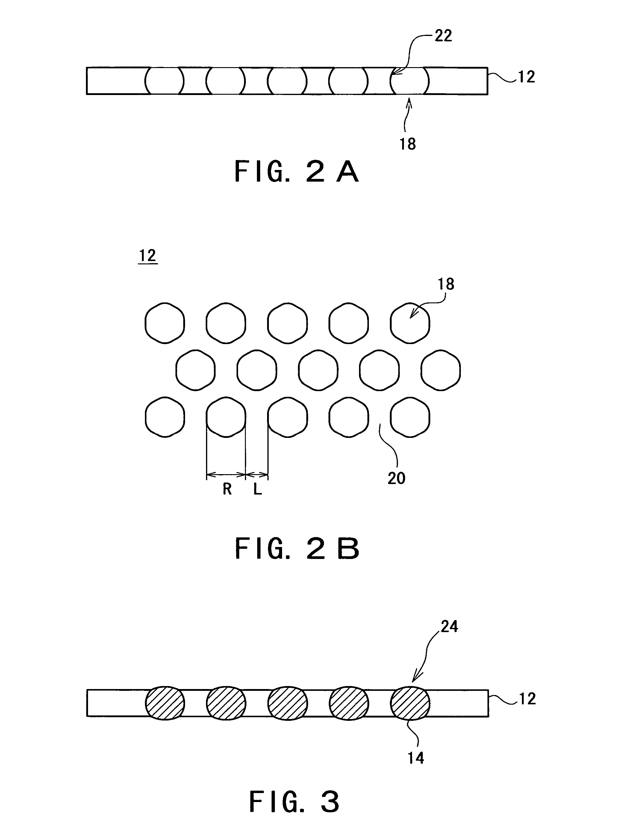
[0137] Next, this polymer solution was cast at a coating film thickness of 780 μm onto a Petri dish (diameter: 90 mm) over which air at a relative humidity of 50% was blown continuously to vaporize the chloroform. As a result, as shown in FIG. 6, a porous film consisting of polysulfone, having numerous holes penetrating in the film thickness direction in a honeycomb arrangement, wherein the inner wall surfaces of the holes curved outwards, was obtained. The diameter of the holes in the porous film was about 5 μm.

[0138] Next, this porous film was immersed in an Ag ethanol dispersion solvent at a concentration of 3 weight % (NIPPON PAINT Co., Ltd., “Fine Sphere SVE 102”, average particle size 50 nm), and lifted up at...

example 2

[0141] An anisotropic conductive film according to Example 2 was manufactured in an identical way to that of Example 1, except that polysulfone was dissolved in chloroform at a concentration of 0.2 weight %, and the coating film thickness was 1560 μm. FIG. 8 and FIG. 9 respectively show a porous film consisting of polysulfone and a porous film wherein the holes were filled with Ag particles, obtained when the anisotropic conductive film according to Example 2 was manufactured. The hole diameter of the porous film was about 10 μm.

example 3

[0142] An anisotropic conductive film according to Example 3 was manufactured in an identical way to that of Example 1, except that instead of polysulfone, siloxane-modified polyimide (UBE INDUSTRIES LTD., “R15”) was dissolved in chloroform at a concentration of 0.1 weight %, and the porous film was lifted up at a speed of 7 μm / sec after immersion in the Ag ethanol dispersion solvent. FIG. 10 and FIG. 11 respectively show a porous film consisting of siloxane-modified polyimide and a porous film wherein the holes were filled with Ag particles, obtained when the anisotropic conductive film according to Example 3 was manufactured. The hole diameter of the porous film was about 5 μm.


PUM

PropertyMeasurementUnit
sizeaaaaaaaaaa
thicknessaaaaaaaaaa
thicknessaaaaaaaaaa

Abstract

To provide an anisotropic conductive film which can respond to increasing pitch reduction of connection targets while maintaining connection reliability, and can be manufactured at a lower cost than conventional, and to provide a method of manufacturing the same. The anisotropic conductive film is provided with a porous film consisting of polymer, having numerous holes penetrating in a film thickness direction, the holes being in a honeycomb arrangement and having inner wall surfaces which curve outwards, a conductive material that fills the holes in the porous film, and an adhesive layer coated on both surfaces of the porous film. The porous film is formed by leaving a supporting substrate on which cast is a polymer solution where a polymer is dissolved in a hydrophobic, volatile organic solvent, under high humidity conditions.

Description

TECHNICAL FIELD [0001] The present invention relates to an anisotropic conductive film and a method of manufacturing the same, and more specifically, to an anisotropic conductive film suitably used for connection of electronic parts and substrates which have a narrow conductor spacing, and a method of manufacturing the same. BACKGROUND ART [0002] In recent years, as electronic equipment becomes more sophisticated and miniaturized, the necessity of electrically connecting plural conductors separated by a narrow pitch is increasing. Such a need exists in the field of liquid crystal displays (LCD), for example when an electrode of a TAB (Tape Automated Bonding) on which a drive IC is mounted in a TCP (Tape Carrier Package), is connected to an electrode of a liquid crystal panel, and when a drive IC is directly connected on a glass substrate of a liquid crystal panel (Chip On Glass: COG). [0003] In these connections, an anisotropic conductive film (ACF) which has conductivity in the fil...

Claims


Application Information

Patent Timeline
Patent Type & Authority Applications(United States)
IPC IPC(8): B32B3/10C09J7/22C09J7/26C09J9/02C09J201/00H01B5/16H01B13/00H01R11/01H01R12/16H01R13/24H01R43/00H05K3/32
CPCC09J7/026C09J7/0289C09J2201/128C09J2201/602H01R13/2414Y10T428/24322H05K2201/0116H05K2201/09945H05K2201/10378H01R12/7076H05K3/323C09J7/22C09J7/26C09J2301/124C09J2301/314C09D179/08C09D5/24H01R11/01C09D179/00
Inventor BESSHO, HISAMISATO, HIDEYUKISATO, AKIOSHIMOMURA, MASATSUGUTANAKA, MASARUYABU, HIROSHI
Owner SUMITOMO RIKO CO LTD
Why Eureka
Try Eureka