Carbon-Based Fuel Cell

a fuel cell and carbon-based technology, applied in the direction of cell components, final product manufacturing, sustainable manufacturing/processing, etc., can solve the problems of reducing the production efficiency of oxygen ions, and reducing the production efficiency of ions, etc., to achieve the effect of promoting the production of oxygen ions

Active Publication Date: 2007-09-13
AKRON UNIV OF
View PDF16 Cites 35 Cited by
  • Summary
  • Abstract
  • Description
  • Claims
  • Application Information

AI Technical Summary

Benefits of technology

[0011] According to yet another aspect, the present invention provides a method of generating electric energy from a solid-state organic fuel. The method comprises the steps of establishing an ionic-communication channel between a cathode and an anode with a solid-oxide electrolyte; providing an electrochemical-oxidation catalyst that includes a sulfur-resistant material to the anode, wherein the electrochemical-oxidati...

Problems solved by technology

The separate gasification and reformation steps required a substantial influx of thermal energy, and heat recovery was low, thereby resulting in an inefficient process.
However, such fuel cells experienced a buildup of fly ash, a byproduct produced from the combustion of solid fossil fuels, on the surface of a catalyst provided to an electrode, and accordingly, a retardation of the fuel cell's performance.
Additionally, these con...

Method used


Image

  • Carbon-Based Fuel Cell
  • Carbon-Based Fuel Cell
  • Carbon-Based Fuel Cell

Examples


example 1

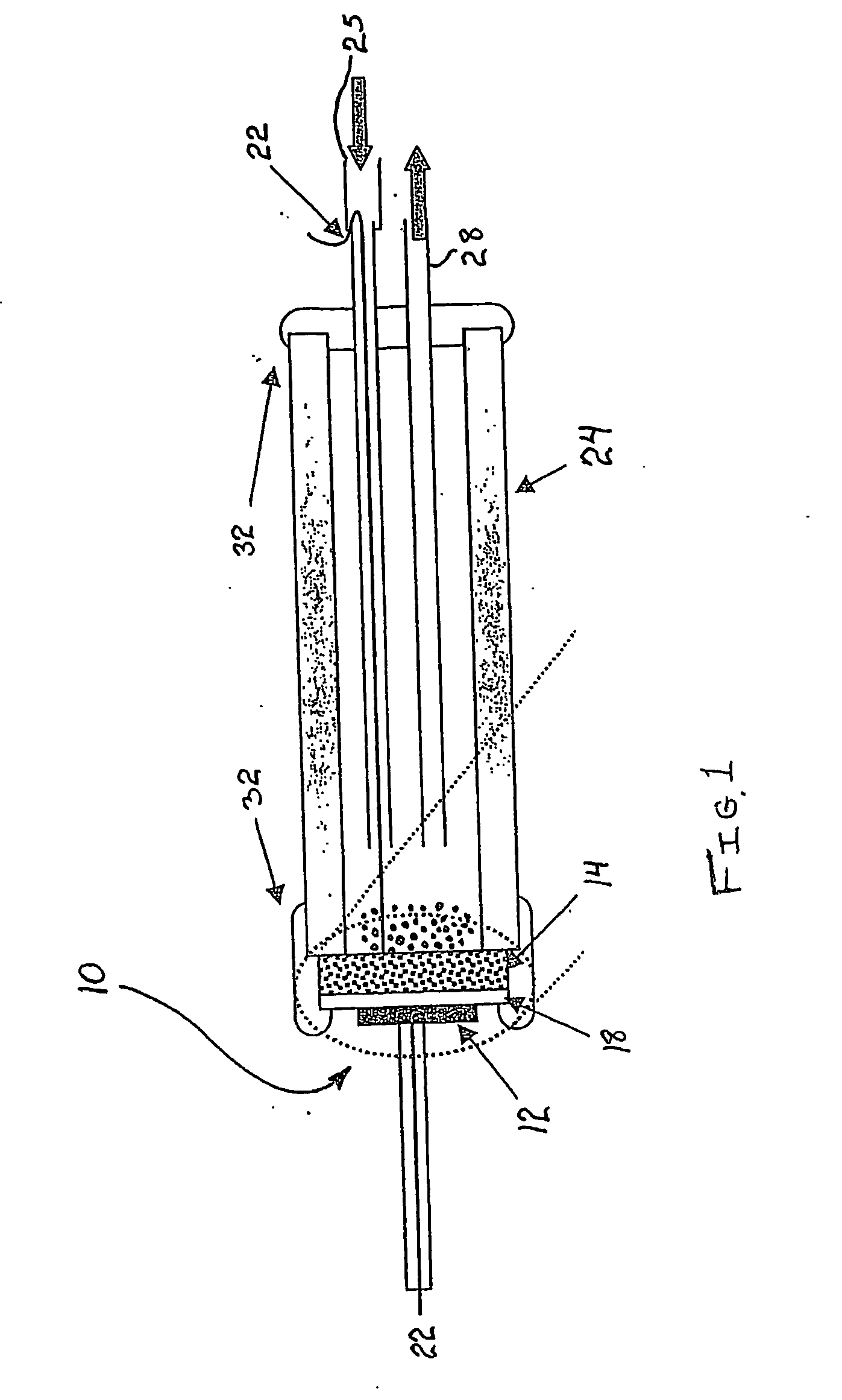
[0048] An experimental assembly including the fuel cell 10 of the present invention is shown in FIG. 3. The fuel cell 10 consists of a dense YSZ disc (from Tosoh Corp.) which is coated with thin layers of anode and cathode catalyst materials that form the electrodes 12, 14. Detailed steps involved in catalyst preparation and fuel cell 10 construction are explained for EXAMPLE 2.

[0049] Both current and voltage output data from the fuel cell 10 were acquired by a PC 50 with an interface and Labview™ software. The gaseous exhaust product was analyzed by a SRI 8610C gas chromatograph 54 and a Pfeiffer QMS 200 mass spectrometer 56. The analysis of gaseous products, such as CO and CO2, allows determination of the fuel conversion efficiency and byproduct formation.

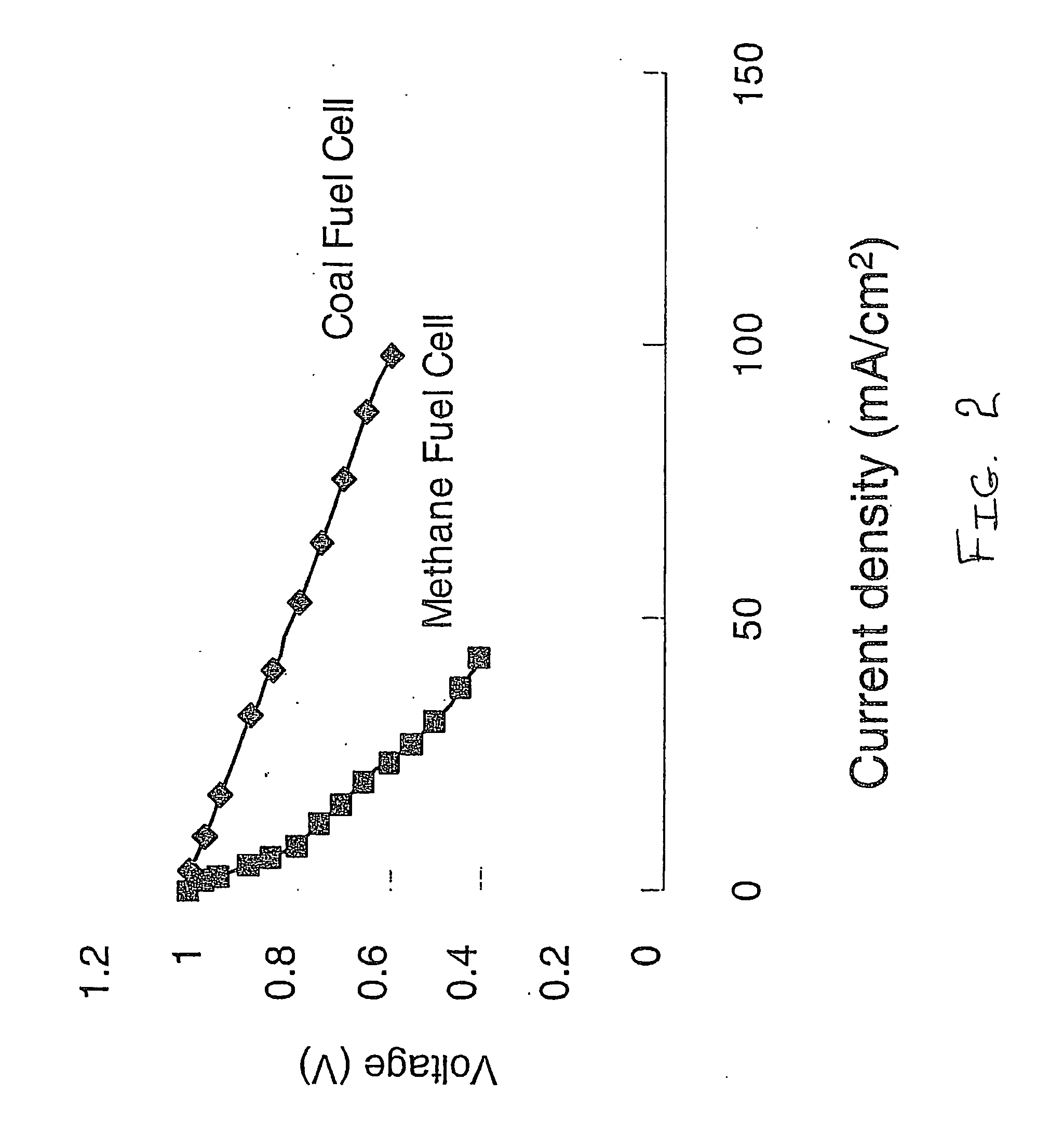
[0050] Referring once again to FIG. 2, the performance (I-V curves) of the fuel cell 10 with the use of pure CH4 and Ohio No. 5 coal (Table 1) as fuels is shown. Using the coal as the solid-state organic fuel, the coal was load...

example 2

Experimental Design

[0057] YSZ disks of 1 mm thickness were purchased from Tosoh Inc. as the solid-oxide electrolyte 18. Material to form the anode 14 and electrochemical oxidation catalyst combination was prepared by impregnation of YSZ fibers (provided by Zircar) and YSZ powder (provided by Tosoh) in a 7:3 ratio with Ni(NO3)2 and NH4ReO4. The nominal weight percentage of the Ni and Re on the anode material is 5 wt % (wt % represents a weight percentage) and 2 wt %, respectively. The anode / electrochemical oxidation catalyst material was pasted on a surface of the YSZ disc (1000 microns) using glycerine and calcined at 1000° C. for 4 hours. This procedure was repeated two times for making a thin layer to form the anode 14.

[0058] The first-electrode material was prepared by mixing Lanthanum Strontium Manganese Oxide (LSM-20, NexTech Materials) and YSZ powder in 1:1 ratio. The first-electrode material was pasted on the YSZ disc to form the cathode 12 using glycerine and calcined at 9...


PUM


Abstract

A direct-electrochemical-oxidation fuel cell and method for generating electrical energy from a solid-state organic fuel. The fuel cell includes a cathode provided with an electrochemical-reduction catalyst that promotes formation of oxygen ions from an oxygen-containing source at the cathode, an anode provided with an electrochemical-oxidation catalyst that promotes direct electrochemical oxidation of the solid-state organic fuel in the presence of the oxygen ions to produce electrical energy, and a solid-oxide electrolyte disposed to transmit the oxygen ions from the cathode to the anode. The electrochemical oxidation catalyst can optionally include a sulfur resistant material.

Description

RELATED APPLICATIONS [0001] This application claims the benefit of U.S. Provisional Application No. 60 / 520,155, filed Nov. 14, 2003; and of U.S. Provisional Application No. 60 / 558,856, filed Apr. 2, 2004.FIELD OF THE INVENTION [0002] The invention relates generally to the generation of electrical energy from a solid-state fuel, and more particularly to a solid-oxide fuel cell for generating electrical energy from a solid-state organic fuel according to a direct electrochemical oxidation of the solid-state organic fuel. BACKGROUND OF THE INVENTION [0003] Conventional solid-oxide fuel cells utilize an electrolyte located between an anode and cathode facilitating the transfer of ions therebetween. Traditionally, solid-state fossil fuels, such as coal, had to be gasified and reformed prior to being introduced to a solid-oxide fuel cell to generate electric energy. Despite the additional processing steps required, the use of such solid-state fossil fuels to generate electricity remained ...

Claims


Application Information

Patent Timeline
IPC IPC(8): H01M12/04H01M4/90
CPCH01M4/8647Y02E60/525H01M4/9025H01M4/905H01M4/9066H01M4/92H01M4/923H01M8/04201H01M8/0637H01M8/0643H01M8/1206H01M8/1233H01M8/1246H01M8/1253H01M8/126H01M8/1266H01M8/22Y02E60/521H01M4/9016H01M8/1231Y02E60/50Y02P70/50H01M8/12H01M8/06
Inventor CHUANG, STEVEN S. C.
Owner AKRON UNIV OF
Why Eureka
Try Eureka