
Production of three-dimensional objects by use of electromagnetic radiation

a technology of electromagnetic radiation and three-dimensional objects, applied in the direction of additive manufacturing processes, electrographic processes, instruments, etc., can solve the problems of sls processes typically having the disadvantage of requiring a focused laser beam, lasers, operating as energy sources, and relatively poor mechanical properties of prototypes, so as to reduce contraction or expansion

Inactive Publication Date: 2007-10-18
Z CORPORATION
View PDF99 Cites 500 Cited by
  • Summary
  • Abstract
  • Description
  • Claims
  • Application Information

AI Technical Summary

Benefits of technology

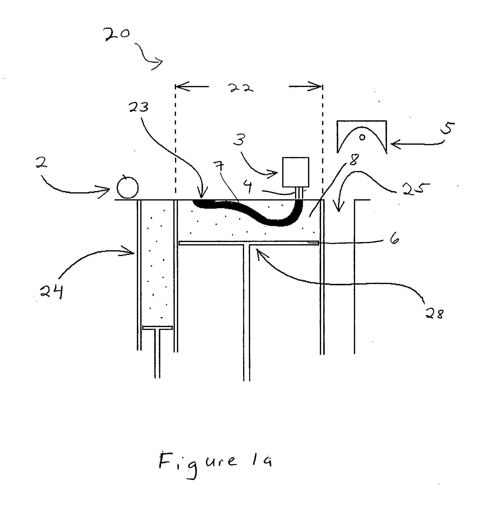
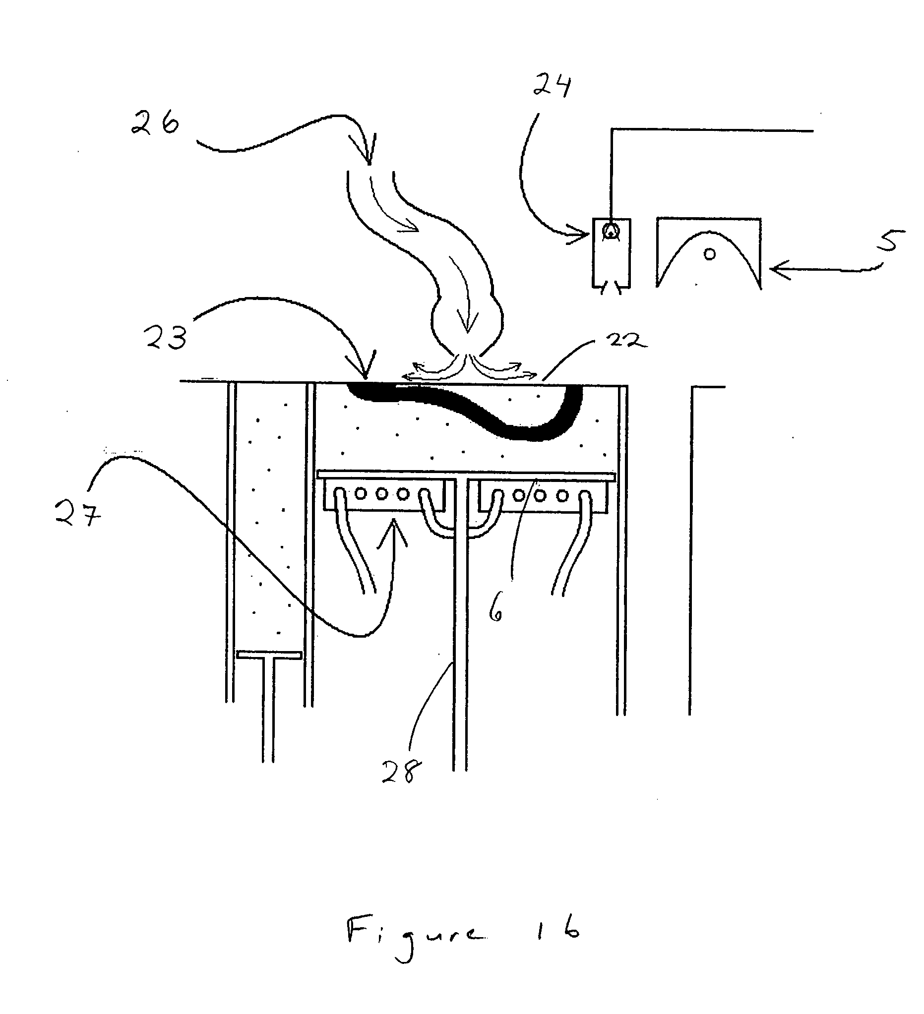
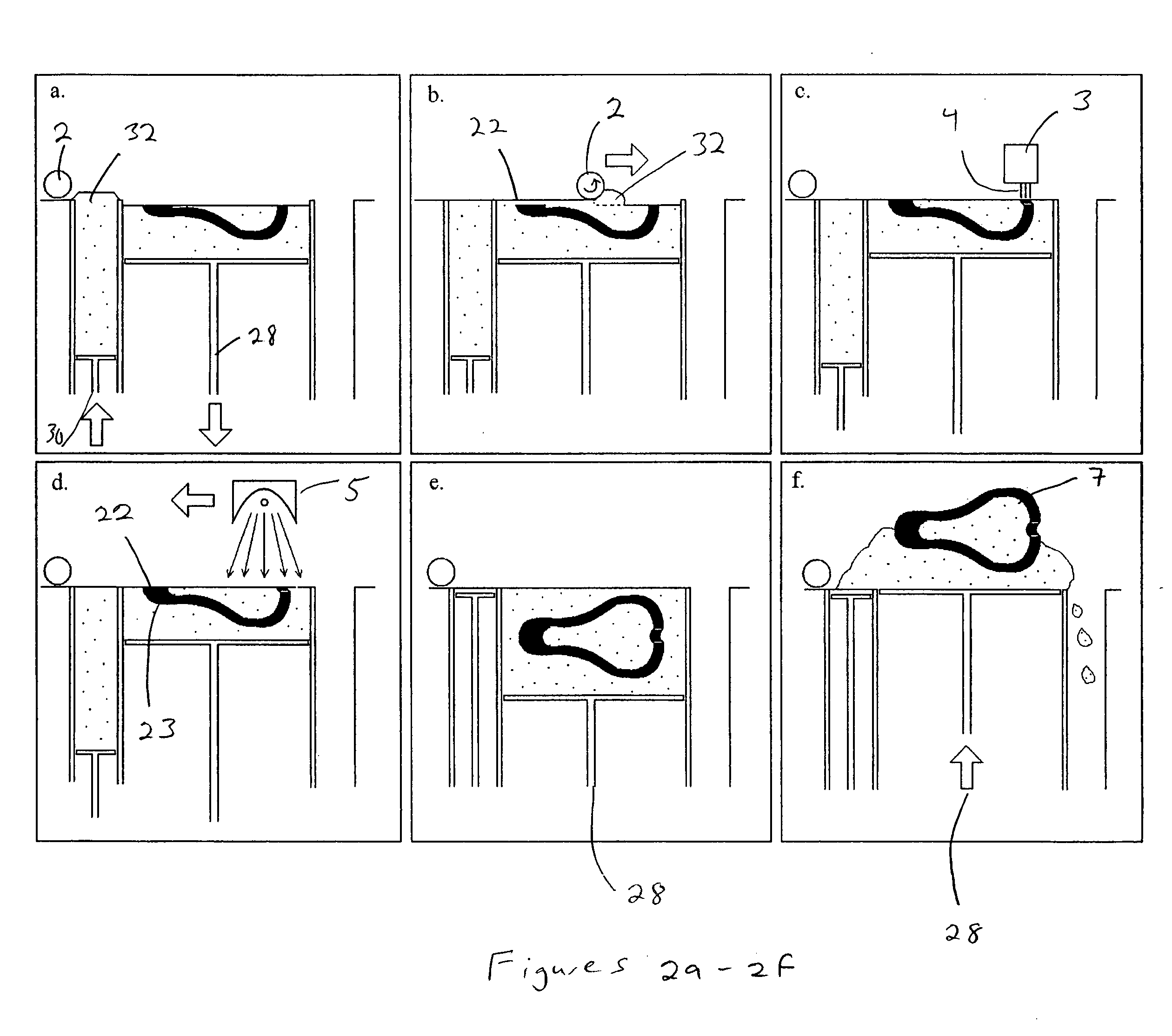
[0011] In an aspect, the invention features a process for the production of three-dimensional objects using a simple, low-cost apparatus that is substantially unsusceptible to failure.
[0021] Thermoplastic and thermoset particulate materials are available as commercial formulations for other processes, such as powder-coating for metal finishing. Many, if not all, currently available formulations may be unsuitable for 3D Printing because the blends sold for other purposes may not fall within a relatively narrow range of particle size and frictional characteristics preferred to enable 3D Printing. A commercial blend of powder-coating material may be rendered useable in the described processes only by further processing, such as by milling and classifying the particulate material, or by adding one or several particulate or liquid additives, or by aggregating or coating thermoplastic compositions onto grains of inert fillers or combinations thereof. The additives may additionally provide some improvement in performance, such as stiffness, but the frictional characteristics of the blend are vitally important in determining their handling properties during spreading and therefore determine the usability of a particular formula.
[0030] The filler may be chemically reactive with a fluid applied to the granular material during three dimensional printing to form a partly bonded structure to reduce contraction or expansion of the first particulate adhesive.

Problems solved by technology

Stereolithography, a process that fabricates models in a bath of liquid photopolymer, needs complicated support structures to retain the solidified material in the liquid bath, and the resultant prototypes have relatively poor mechanical properties, attributable to a limited number of starting materials.
The SLS processes typically have the disadvantage of requiring a focused laser beam.
The laser, functioning as energy source, may be expensive and sensitive, as is the optical equipment needed for the production and focusing of the laser beam, such as lenses, expanders, and deflector mirrors.
Other processes have been developed for rapid prototyping, but have not been introduced to the market.
A disadvantage of this process is that the surrounding particulate material that was not sintered still contains the inhibitor, and therefore, cannot be recycled.
In addition, this process may require the development of new software, specifically because it is the surrounding area that is printed, and not, as in other cases, the cross section of the part.
In addition, there is a risk of heat build up in the developing prototype.
This process may also require complicated technology to ensure that the microwave radiation reaches only the selected regions.
Prototyping methods that use focused sources of radiation are relatively expensive and complicated and may require frequent maintenance.
Microwave radiation, however, may be troublesome to contain, particularly in situations where electronic components are in close proximity to the microwave source.
Further, this approach poses little opportunity to control the undesirable flow of heat by direct conduction from bonded regions into adjacent unbound regions within the particulate material bed.

Method used


Image

  • Production of three-dimensional objects by use of electromagnetic radiation
  • Production of three-dimensional objects by use of electromagnetic radiation
  • Production of three-dimensional objects by use of electromagnetic radiation

Examples


example 1

[0249] Production of a tensile specimen using polyolefin based composition.

[0250] Using the apparatus described above, a tensile specimen was made using a dry free-flowing particulate composition containing 17.0% of polypropylene (Microthene FP-8090 average particle size 20 μm) and 83.0% of aminosilane-modified glass beads (Potters Industries 3000E) as a build material. The absorber was zb®56 binder from Z Corporation containing 2.0% solids by weight of chemically modified carbon black (Cab-O-Jet IJX352B). A total of 16 layers were printed, and each layer in turn was irradiated by a 500-watt tungsten-halogen lamp (5″ length) that traveled over the build area at a speed of 17.7 mm / sec. Layer thickness was 0.10 mm and volume fraction of the absorber fluid was 0.19.

[0251] Final part had tensile strength of 5.76 MPa and elongation at break of 4.5%

example 2

[0252] Production of a tensile specimen, a flexural strength specimen and a 50-layer thick part using thermoset epoxy containing inert filler.

[0253] In this example, the build material consisted of 29.6% granulated epoxy: Everclear® EFC500S9 from Dupont, and 70.4% by weight of 75 μm diameter glass beads (Potter Industries 3000E grade). Absorber fluid, volume fraction of the absorber fluid and build layer thickness and were the same as in Example 1. The tungsten-halogen lamp used in Example 1 was traversed over each printed layer at a speed of 20.3 mm / sec. At the completion of the build process, the partially bonded object was removed from the surrounding unbound material and heat-treated in the convection oven for 2 hours at 95 Celsius. After heat treatment the flexural strength of the material was 54 MPa; tensile strength 35 MPa, elongation at break 2.2%. A 50-layer part had good dimensional stability but had issues with caking (build material from the unprinted areas melted on th...

example 3

[0254] Production of the tensile specimen using a fast-drying PVA system.

[0255] In this example the build material consisted of 20% milled polyvinyl alcohol with a mean grain size approximately 100 microns, and 80% of aminosilane-modified glass beads glass beads (Potter Industries “Spheriglass” 2530 CP03 grade). Absorber fluid, volume fraction of the absorber fluid and build layer thickness and were the same as in Example 1. The tungsten halogen lamp used in Example 1 passed over each printed layer twice at the speed of 12.7 mm / sec. Tensile strength of the specimen was 6.4 MPa and elongation at break 2.6%. The same material was printed without passing the light source over the printed layer. After 16 hours drying in the printing bed the part was soft and impossible to handle.


PUM

PropertyMeasurementUnit
Lengthaaaaaaaaaa
Nanoscale particle sizeaaaaaaaaaa
Wavelengthaaaaaaaaaa

Abstract

Process, materials, and equipment for producing three-dimensional objects from a particulate material by melting and adhering, for example, by fusion or sintering, portions of the particulate material.

Description

RELATED APPLICATION [0001] This application claims the benefit of and priority to U.S. Provisional Application Ser. No. 60 / 789,758 filed Apr. 6, 2006, the entire disclosure of which is hereby incorporated by reference.FIELD OF THE INVENTION [0002] The invention relates to a process for producing three-dimensional objects from a particulate material by melting and adhering, for example, by fusion or sintering, portions of the particulate material; the heat needed for the bonding of the particulate material may be generated by a laser, or a non-oriented and / or non-monochromatic and / or non-coherent energy source of wavelength from 100 nm to 1 mm or by electromagnetic induction by way of an absorber, and transferred by way of the absorber to the subregions of the particulate material. Additionally, heat may be supplied by a chemical reaction between reactive components in the fluid, particulate material, or both. BACKGROUND [0003] There is a need for the rapid production of prototypes. ...

Claims


Application Information

Patent Timeline
IPC IPC(8): B29C71/04B29C35/08
CPCB29C67/0066B29C67/007B29K2105/16B29K2101/12B29K2101/10G03G15/224B29C64/165C04B2111/00181
Inventor GILLER, EUGENEBREDT, JAMES F.DAVIDSON, TOMWILLIAMS, DEREK X.ALAM, AMIRBERRINGTON, BENJAMIN
Owner Z CORPORATION
Learn More