Lighting Device And Method

a technology of light source and light source, which is applied in the direction of lighting and heating apparatus, printed circuit non-printed electric components association, light absorption dielectrics, etc., can solve the problems of reducing performance, hbled has a longer useful life, and hbled has a longer useful life, and achieves excellent heat sink properties

Inactive Publication Date: 2007-11-08
HEATRON
View PDF1 Cites 38 Cited by
  • Summary
  • Abstract
  • Description
  • Claims
  • Application Information

AI Technical Summary

Benefits of technology

[0014] The present invention provides a new and improved apparatus for use as a light emitting diode (LED) lighting device. The present invention provides a robust support for LEDs that affords excellent heat sink properties and the ability to laser trim circuitry without risk of damaging the underlying substrate. The invention may include a high temperature coating layer having controlled reflectance that offers long-term color stability and reflectivity. The apparatus includes a metal substrate having a surface with a dielectric coating layer disposed on the surface of the metal substrate. A light emitting diode (LED) is supported on the dielectric coating layer. The metal substrate serves as a heat sink for the heat emitted by the LED during operation of the device.

Problems solved by technology

Coatings commonly used to enhance the circuit board reflectivity can have long-term stability problems, such as diminished performance in high ultraviolet (UV) conditions, deterioration due to weathering, sensitivity to high temperatures, and age induced yellowing.
The HBLED has a longer useful life and consumes less power than a comparable LED.
Accordingly, the efficiency of the LED to shed heat limits the brightness attainable by the LED.
However, the heat from the trimming operation can damage PCBs formed of traditional reinforced plastics.
This susceptibility to heat damage limits the usefulness of resistor trimming in PCB applications.

Method used


Image

  • Lighting Device And Method
  • Lighting Device And Method
  • Lighting Device And Method

Examples


first embodiment

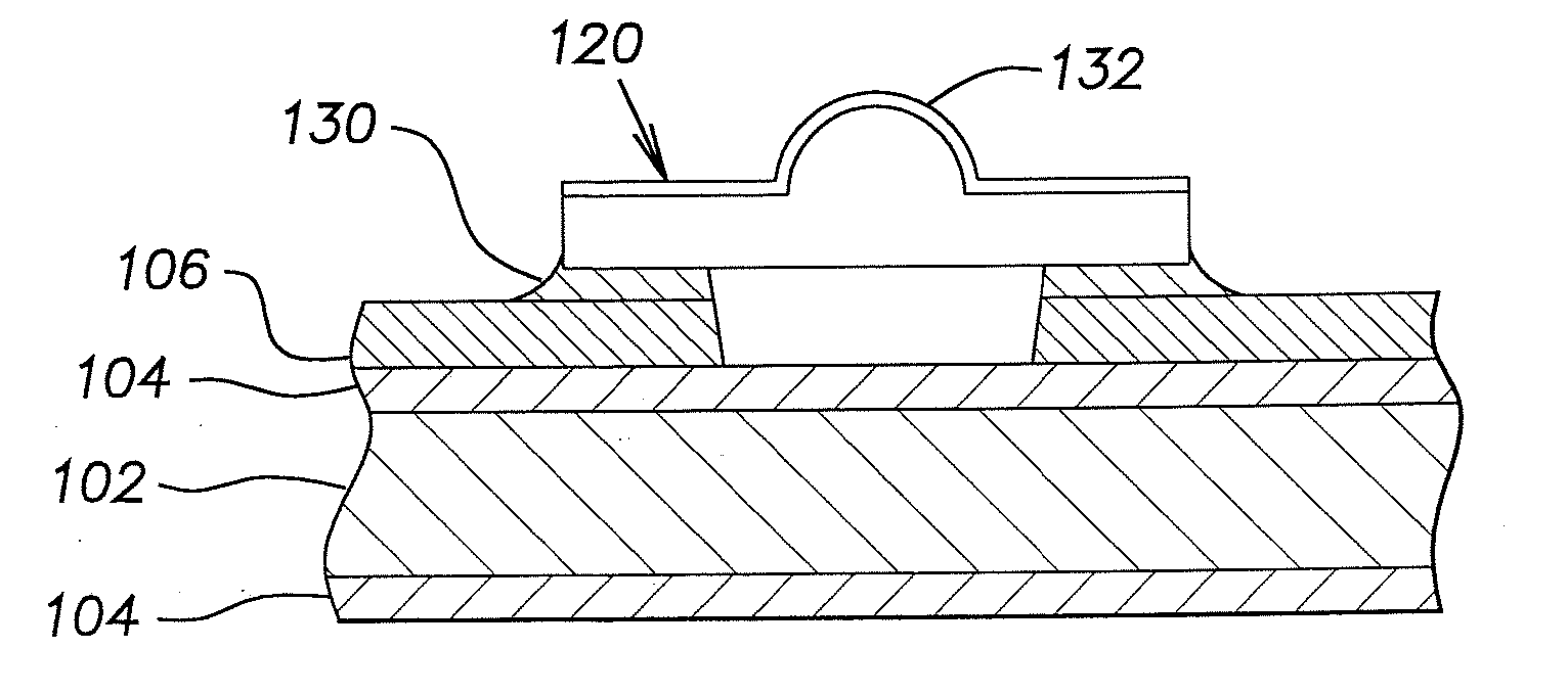
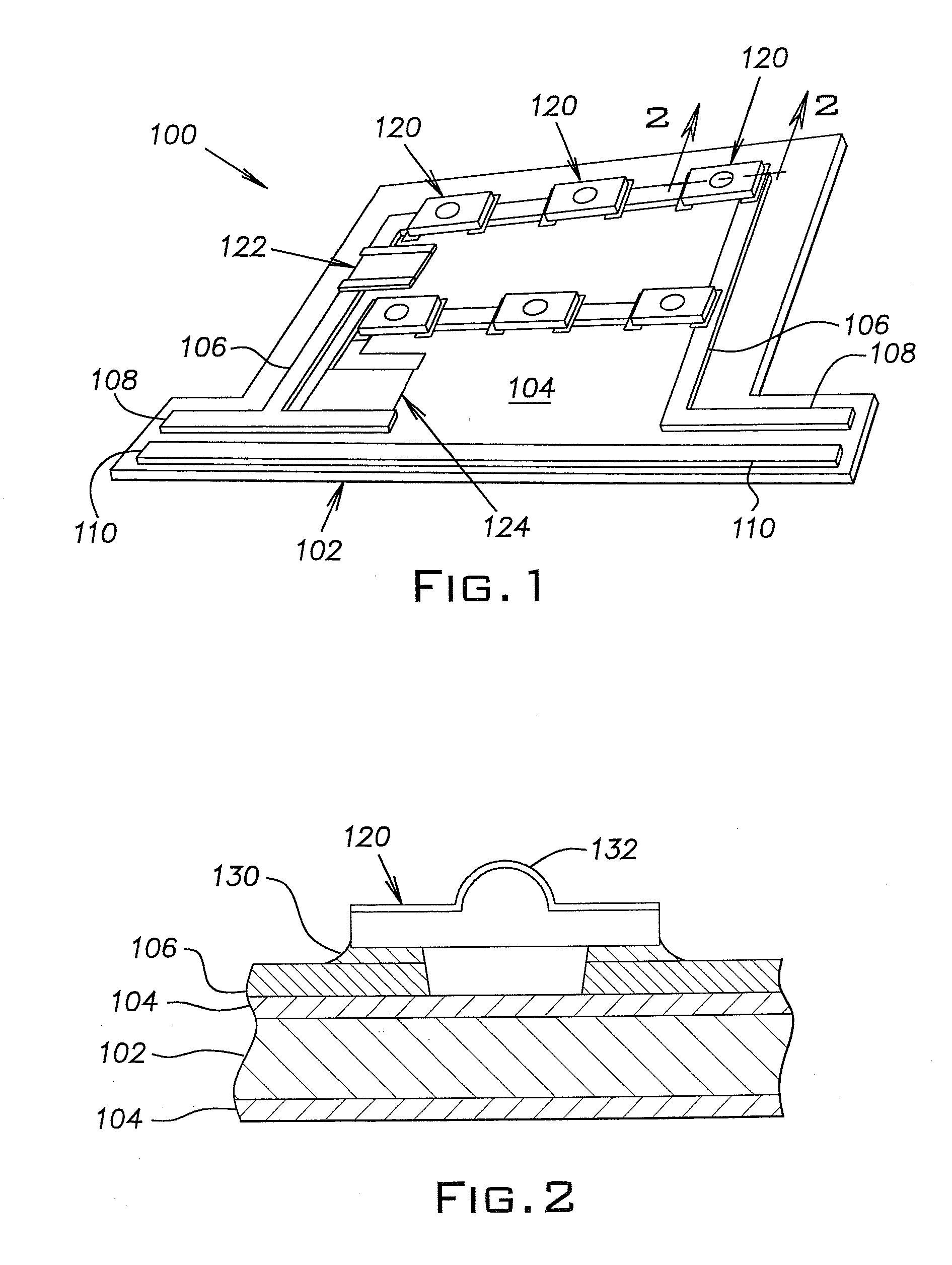
[0024] A light emitting apparatus 100 comprising the invention is shown in FIG. 1. The apparatus 100 is a lighting device including light emitting diodes (LEDs) on an electrically insulated metal substrate. Specifically, the apparatus 100 is an LED light engine for use in applications such as signage and lighting displays.

[0025] With reference to FIGS. 1-2, the apparatus 100 includes a metal substrate indicated generally by reference numeral 102. An inorganic porcelain enamel layer 104 over-coats the metal substrate 102 to form an electrically insulating dielectric layer. Electronic circuits 106 are arranged on the enamel layer 104. The electronic circuits 106 communicate first and second electronic leads 108, 110 with a plurality of light emitting diodes 120. First and second resistors 122, 124, in series with the LEDs 120, communicate with the first electronic lead 108 through the circuits 106.

[0026] In this embodiment, the metal substrate 102 is low carbon decarburized steel. Th...

second embodiment

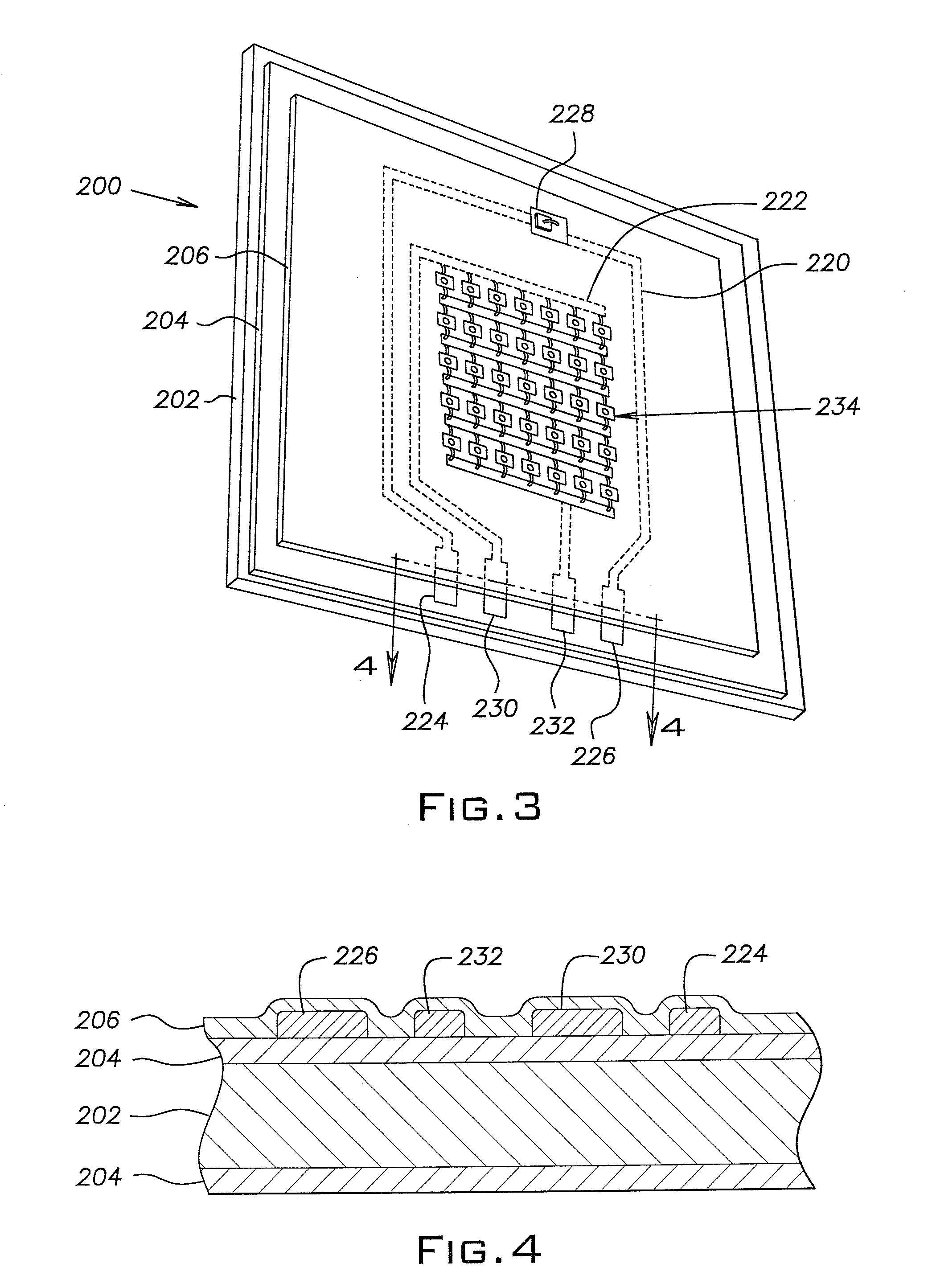
[0037] With reference to FIG. 3, an apparatus 200 comprising the invention is shown. The apparatus 200 is an LED light engine similar to the light engine of the apparatus 100. The light engine 200 includes a metal substrate 202 comprising decarburized low carbon steel.

[0038] A porcelain enamel coating 204 forms a dielectric layer over the surface of the metal substrate 202. A reflective inorganic enamel coating 206 forms a white reflective layer superimposed over the enamel coating layer 205. In applications where the reflectivity of light is desired, a white coating is employed. Preferably, the white coating displays a reflectivity of at least 80%. Various white enamel coating material systems are commercially available from companies such as the Ferro Glass & Color Corporation of Washington, Pa. Applicants believe that an enamel having high reflectivity is best achieved by the formulation of a ball milled enamel powder comprising by weight 1000 parts 14390 glass frit available fro...

third embodiment

[0045] In FIG. 5, an apparatus 300 comprising the invention is shown. The apparatus 300 includes a decarburized steel substrate 302. An electrically insulative dielectric layer 304 coats the metal substrate 302. Superimposed on a portion of the coating layer 304 is an inorganic white layer 306. However, it will be appreciated that any number of colored (controlled reflectance) enamels, such as black enamel, may be employed depending upon the desired reflectivity properties. High temperature enamels in various colors are available from the Ferro Corporation.

[0046] A plurality of unpackaged LEDs each include a gold wire 310 and an InGaN semiconductor chip 314. The chip 314 is adhered by an adhesive layer 316 to a first thick film, conductive printed circuit 318. The wire communicates with a second thick film, conductive printed circuit 320.

[0047] During operation, a negative (−) electrical potential is applied to the first circuit 318 and a positive (+) electric potential is applied ...


PUM

PropertyMeasurementUnit
temperatureaaaaaaaaaa
bonding temperatureaaaaaaaaaa
temperatureaaaaaaaaaa

Abstract

A lighting device having a light emitting diode (LED). The device includes a metal substrate having a surface. A dielectric coating layer is superimposed on the surface of the metal substrate. A light emitting diode (LED) is supported on the dielectric coating layer. The metal substrate serves as a heat sink for the heat emitted by LED during operation.

Description

[0001] This application is a continuation filing of application Ser. No. 10 / 120,158 filed Apr. 10, 2002 which is incorporated herein by reference in its entirety.BACKGROUND [0002] 1. Technical Field [0003] The present invention relates generally to a lighting device including a light emitting diode supported on an electrically insulated metal substrate. [0004] 2. Description of Prior Art [0005] A light emitting diode (LED) includes a semiconductor chip that emits light and heat in response to the application of an electrical current. There are two major types of LEDs, “packaged” and “unpackaged.” A packaged LED is one with a solderable lead and a reflector cup. In a packaged LED, a semiconductor chip, for example an Indium Gallium Nitride (InGaN) or Indium Phosphide (InP) semiconductor chip, is housed in the reflector cup inside an optically transparent epoxy shell. [0006] An unpackaged LED is also available. An unpackaged LED has a bare die, that is, the semiconductor chip has no s...

Claims


Application Information

Patent Timeline
Patent Type & Authority Applications(United States)
IPC IPC(8): H01L33/00F21K99/00H01L33/64H05K1/02H05K1/05H05K1/09H05K1/16H05K1/18
CPCH01L33/64H05K1/0203H01L2224/45144H01L2224/73265H01L2224/48472H01L2224/48227H01L2224/48091H05K2201/2054H05K2201/10106H05K1/053H05K1/092H05K1/167H05K1/18H05K1/181H05K2201/0112H01L2924/00014H01L2924/00
Inventor MARTTER, ROBERT H.SUNDBERG, CRAIG C.GIARDINA, RICHARD N.FETSCHER, BRIAN S.DEUTSCHLANDER, G. JAMES
Owner HEATRON
Why Eureka
Try Eureka