
Metal Oxide Electrode Catalyst

a metal oxide electrode and catalyst technology, applied in the field of electrochemical catalysts, can solve the problems that the catalytic activity of metal oxides itself has not been evaluated in detail, and achieve the effect of high corrosion resistan

Inactive Publication Date: 2007-11-08
JAPAN SCI & TECH CORP
View PDF3 Cites 11 Cited by
  • Summary
  • Abstract
  • Description
  • Claims
  • Application Information

AI Technical Summary

Benefits of technology

[0028] A corrosion-resistant electrode catalyst for oxygen reduction according to the present invention has high corrosion res

Problems solved by technology

However, the catalytic activity of metal oxides themselves has not been evaluated in detail.

Method used


Image

  • Metal Oxide Electrode Catalyst
  • Metal Oxide Electrode Catalyst
  • Metal Oxide Electrode Catalyst

Examples


example 1

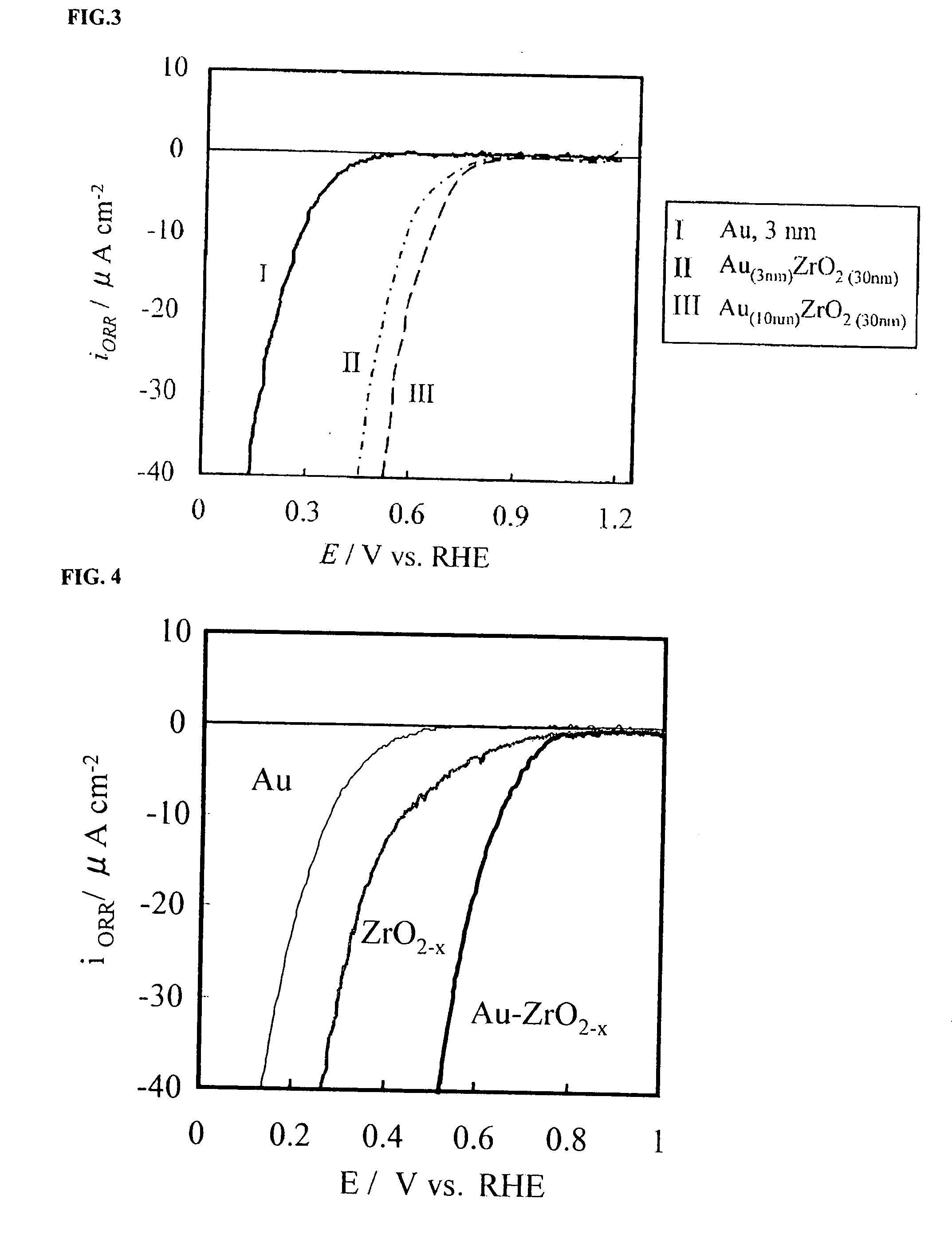
[0045] Using a glassy carbon cylinder with a diameter of 5.2 mm, a gold layer of 10 nm was first formed on a bottom face thereof by a double sputtering technique. Then, a metal oxide electrode catalyst layer was formed by sputtering, the metal oxide including zirconium as the transition metal. An Au—ZrO2-x electrode catalyst was thereby produced. The helium pressure during sputtering was set at 1×10⁻³ Pa or less. Au and stoichiometric zirconium oxide were used as sputtering targets.

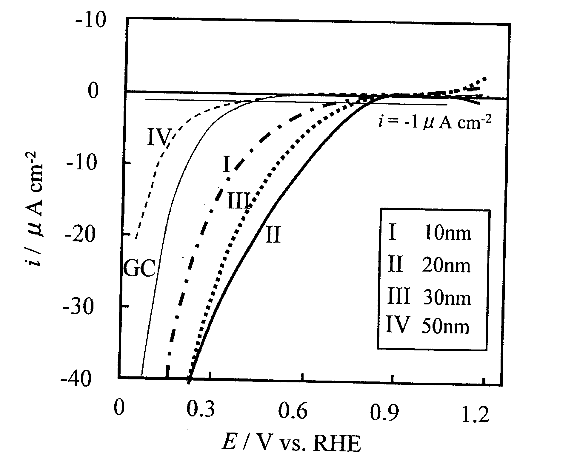
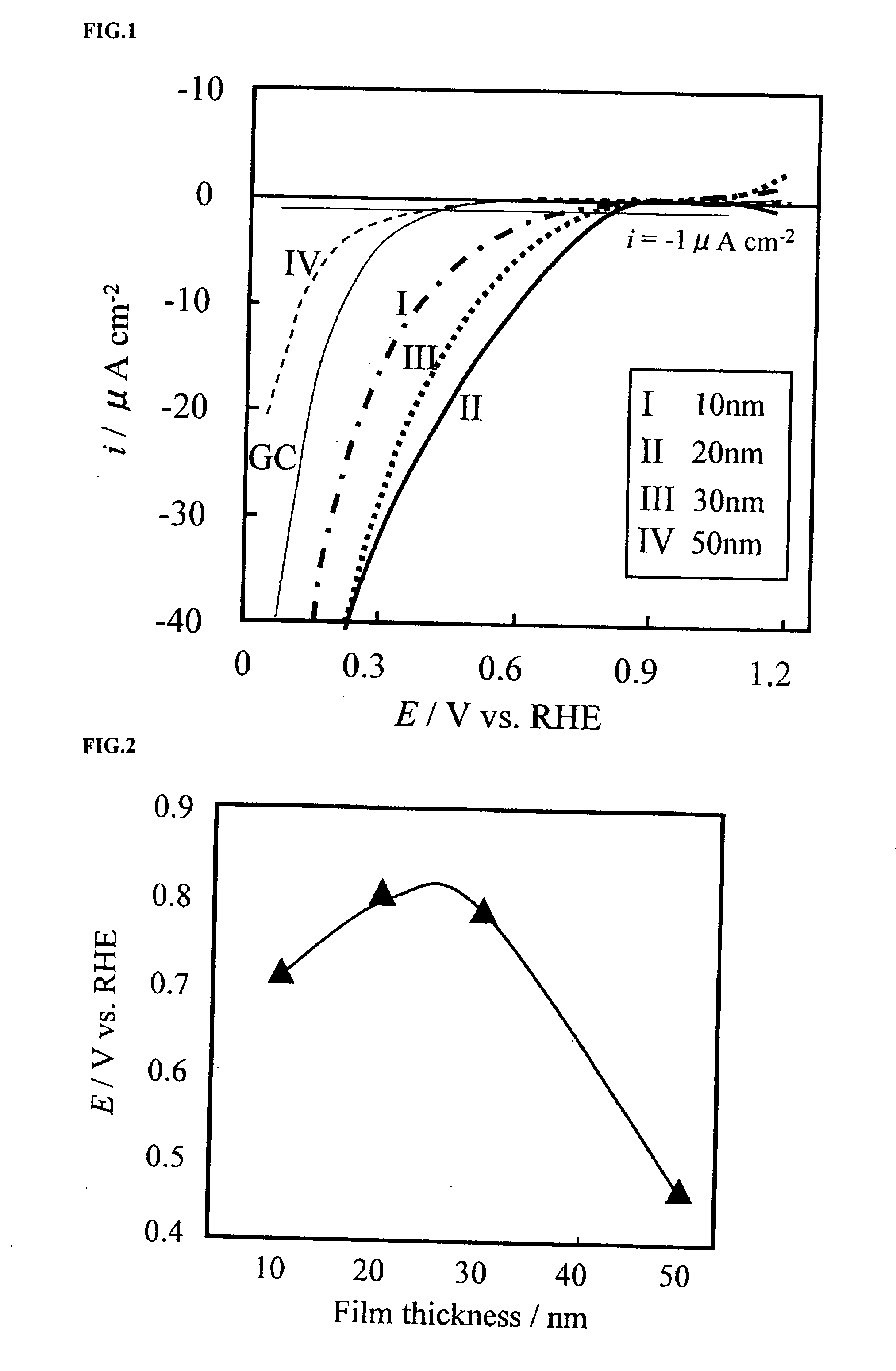
[0046] Using a quartz oscillation-type film thickness meter, the amount of sputtering was measured. A zirconia oxide electrode with a zirconia oxide film thickness of about 30 nm was formed. The atomic compositional ratios between zirconium and oxygen at the surface and in the interior were identified by XPS. The results thereof are shown in Table 1 below.

TABLE 1SurfaceInteriorElementOZrOZrCompositional67.932.162.137.9ratio (%)

[0047] The atomic compositional ratios between Zr and O calculated from Tabl...

example 2

[0050] An Au—NbO5-x electrode catalyst was produced under the same conditions as in Example 1 except that niobium was used as the transition metal. The catalytic activity of the resulting Au—NbO5-x electrode was evaluated in relation to an oxygen reduction reaction under the same conditions as in Example 3. FIG. 5 shows the current-potential curve of the resulting Au—NbO5-x electrode in comparison with an Au only electrode and a NbO5-x electrode. It is evident that the oxygen reduction activity of the NbO5-x electrode was improved by the Au layer.

example 3

[0051] An Au—SnO2-x electrode catalyst was produced under the same conditions as in Example 1 except that tin was used as the transition metal. The catalytic activity of the resulting Au—SnO2-x electrode was evaluated in relation to an oxygen reduction reaction under the same conditions as in Example 3. FIG. 6 shows the current-potential curve of the resulting Au—SnO2-x electrode in comparison with an Au only electrode and a SnO2-x electrode. It is evident that the oxygen reduction activity of the SnO2-x electrode was improved by the Au layer.


PUM


Abstract

A corrosion-resistant electrode catalyst for oxygen reduction includes a main catalyst composed of at least one transition metal oxide selected from oxygen-deficient ZrO2, Ta2O5, Nb2O5, TiO2, V2O5, MoO3, and WO3 and a co-catalyst composed of gold. The electrode catalyst is used in contact with an acidic electrolyte at a potential at least 0.4 V higher than the reversible hydrogen electrode potential. The catalyst may be used, for example, in such a form that the transition metal oxide in the form of fine particles and gold in the form of fine particles, or fine particles including fine gold particles coated with the transition metal oxide are dispersed on a catalyst carrier which is an electron conductive powder. This electrode catalyst is suitable as an electrode catalyst for an electrochemical system using an acidic electrolyte in the fields of water electrolysis, inorganic / organic electrolysis, fuel cells, etc.

Description

TECHNICAL FIELD [0001] The present invention relates to electrode catalysts for oxygen reduction for electrochemical systems which use acidic electrolytes in the fields of water electrolysis, inorganic / organic electrolysis, fuel cells, etc. More particularly, the invention relates to an electrode catalyst for oxygen gas diffusion electrodes of fuel cells which use solid polymer electrolyte membranes. BACKGROUND ART [0002] Noble metals, in particular, platinum, are stable over a wide potential range and have high catalytic activity for various reactions, and thus are used as electrode catalysts for various electrochemical systems. [0003] Some metal oxides are stable in acidic electrolytes over a wide potential range. Therefore, research has been conducted on enhancing the catalytic activity of platinum by allowing metal oxides to coexist with platinum (for example, Non-patent Documents 1 and 2, and Patent Document 1). However, the catalytic activity of metal oxides themselves has not...

Claims


Application Information

Patent Timeline
IPC IPC(8): H01M4/58H01M4/86H01M4/90H01M8/10
CPCH01M4/8605Y02E60/521H01M8/1002H01M4/9016H01M8/1007Y02E60/50
Inventor OTA, KENICHIROKAMIYA, NOBUYUKIMITSUSHIMA, SHIGENORIISHIHARA, AKIMITSUYAN, LIU
Owner JAPAN SCI & TECH CORP
Learn More