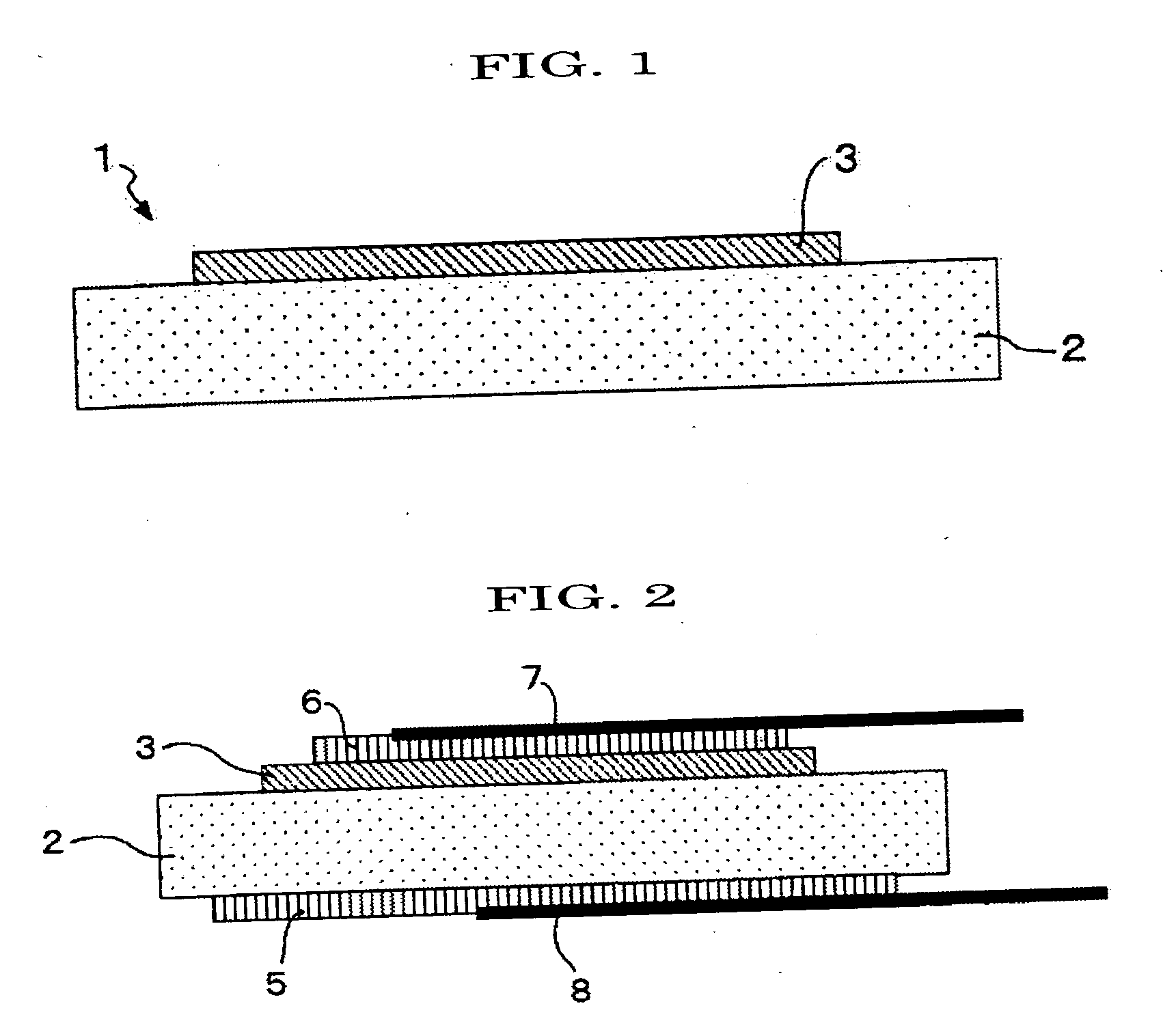
Thermistor Device

a technology of thermosensors and resistors, which is applied in the direction of resistors, positive temperature coefficient thermistors, semiconductor devices, etc., can solve the problems of small resistance difference at or near operating temperature drawback, poor high-speed response to temperature change, and small on/off ratio, etc., to achieve high on/off ratio, small size, and high temperature response speed

Inactive Publication Date: 2007-11-15
NEC SCHOTT COMPONENTS CORP +1
View PDF5 Cites 20 Cited by
  • Summary
  • Abstract
  • Description
  • Claims
  • Application Information

AI Technical Summary

Benefits of technology

[0033] The present invention can provide a thermistor device having a high-speed response to temperature and a high ON / OFF ratio at or near operating temperature.
[0034] Further, the present invention can provide a thermistor apparatus which is small in size and has a high-speed response to temperature, a variable and controllable operating temperature, and a variable and controllable ON / OFF ratio at or near operating temperature.
[0035] The present invention will be described in detail hereinafter.
[0036] The thermistor device of the present invention comprises a first layer comprised of a first substance having a positive or negative temperature coefficient of resistance and a second layer comprised of a second substance having conductivity or semiconductivity and located directly on the first layer.
[0037] A typical constitution example of the thermistor device of the present invention is shown in FIG. 1. In FIG. 1, a thermistor device 1 comprises only a first layer 2 consisting of a first substance having a positive or negative temperature coefficient of resistance and a second layer 3 formed directly on the first layer 2.
[0038] In the thermistor device according to the present invention, the first layer may be comprised of a first substance having a positive or negative temperature coefficient of resistance, preferably, a first substance having a positive temperature coefficient of resistance.

Problems solved by technology

These PTC devices had problems as described below: In the above item 1), resistance is too high because it is a semiconductor under low resistance condition; and in the above item 2), a principle is used in which with increase in temperature, an organic polymer as a matrix swells, thereby increasing the distance between carbon black particles as a filler, resulting that the resistance raises up at higher temperatures, and since a response to temperature changes depends on swelling of an organic polymer; thus, a high-speed response to temperature change is poor.
However, during rising temperature condition i) substances showing positive change in resistance are rare, and even in such a case, ii) small ON / OFF ratio at operating temperature, namely, small difference in resistance at or near operating temperature is drawback.

Method used


Image

  • Thermistor Device
  • Thermistor Device
  • Thermistor Device

Examples


example 1

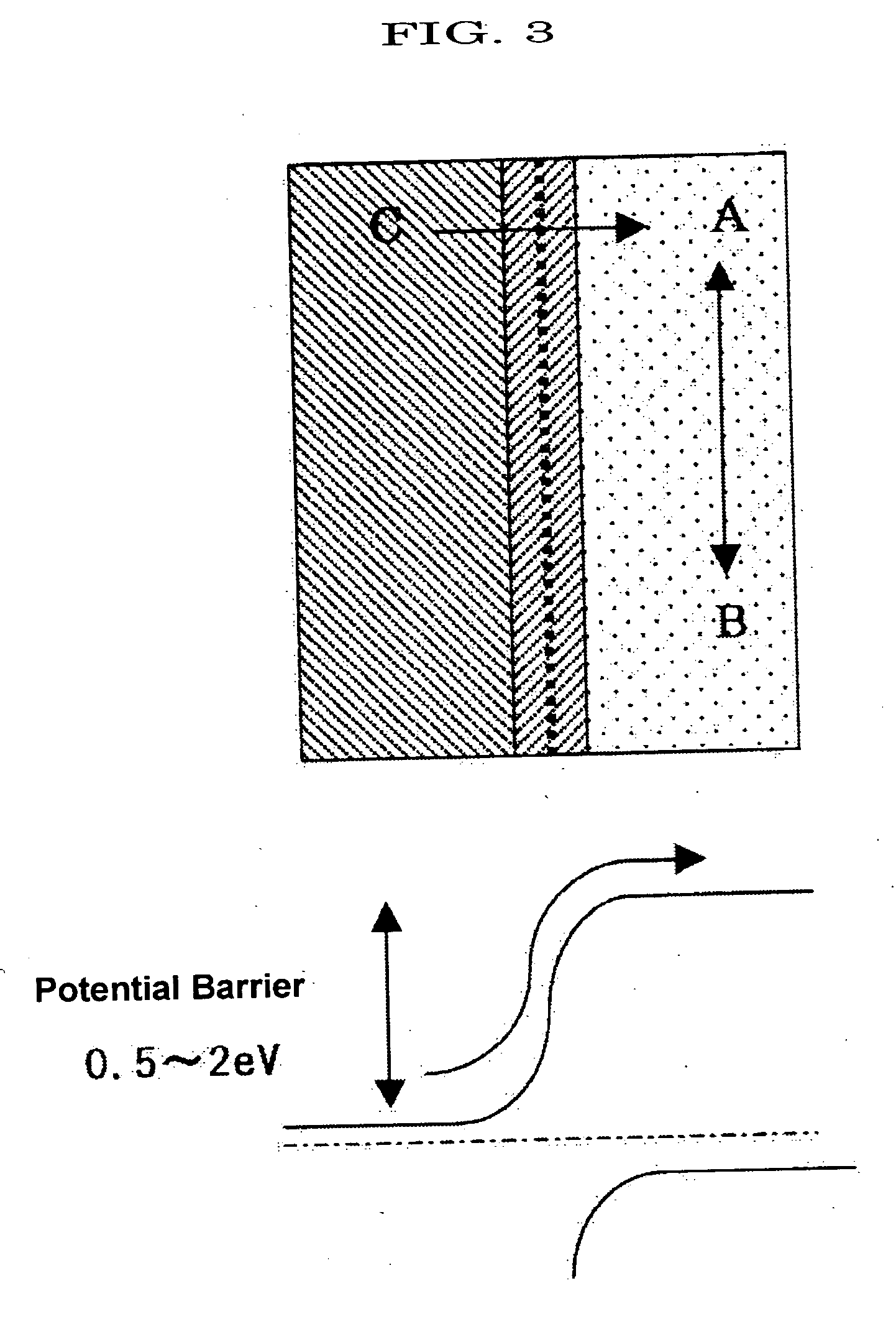
[0051] ZnO (thickness: 400 nm) was used as the second layer, and a (V0.988Cr0.011)2O3 polycrystal was prepared by an arc melting process as the first layer on the ZnO, obtaining a (V0.988Cr0.011)2O3 / ZnO junction type thermistor device A-1. For this device A-1, a change in current-voltage property (I-V property) depending on temperature was measured.

[0052] The I-V property of the device A-1 is linear below the phase transition temperature (TM-I=290 K) of (V0.988Cr0.011)2O3, and shows non-linearity at 290 K or higher. FIG. 4 shows a result at 250 K as the I-V property of the device A-1 at 290 K or lower, and a result at 306 K as the I-V property at 290 K or higher, suggesting formation of a potential barrier at the interface between the first and second layers of the device A-1. In the I-V property of the device A-1, current passing through the interface is out of the ohmic property up to around 0.7 V at temperatures of 290 K or higher (for example, result at 306 K in FIG. 4), and no...

example 2

[0055] Since a commercially available V2O3 powder is oxidized and its stoichiometry deviation would be occurred during preservation, it was reduced by heating at 900° C. for 5 hours under a reducing atmosphere (Ar:H2=95:5 (volume ratio)) to return to stoichiometric composition. The composition was confirmed by X-ray diffraction.

[0056] Chromium nitrate nona-hydrate was weighed in stoichiometric amount (1 mol %), and mixed well with a reducing agent V2O3 powder by wet mixing using acetone so that V:Cr=99:1 (atom %). After mixing, the mixture was calcined at 900° C. for 10 hours under a reducing atmosphere (Ar:H2=95:5 (volume ratio)), obtaining a polycrystalline powder by a solid phase reaction. Thereafter, the powder was mixed well again.

[0057] 0.6 g of the resulting polycrystalline powder and tellurium chloride (TeCl4) as a transporting agent were added into a quartz tube having a total length of 200 mm with a diameter of 12.5 mm, and the tube was sealed under vacuum (approximately...


PUM


Abstract

A thermistor device having a high-speed response to temperature and a large ON/OFF ratio at the operating temperature. The thermistor device comprises a first layer of a first material having a positive temperature coefficient of resistance and a second layer of a second material having a semiconductivity and formed directly on the first layer. As the first material changes from conductive to a semiconductive or an insulative at or near the transition temperature TM-I, the interface between the first and second layer changes to a pn junction.

Description

TECHNICAL FIELD [0001] The present invention relates to a temperature sensor, infrared sensor, overcurrent preventing device, temperature control device and temperature switch, utilized for the control of electric or electronic apparatuses. BACKGROUND ART [0002] Conventionally, there have been suggested 1) semiconductive BaTiO3 PTC thermistor devices obtained by doping a rare earth element such as La, Gd and the like into BaTiO3 as a ferroelectric substance; and 2) PTC devices obtained by dispersing conductive carbon black particles as a filler in an organic polymer substance as a matrix (see, Patent Document 1) as devices manifesting a so-called “PTC (Positive Temperature Coefficient)” resistance property showing insulating property at high temperatures and conducting property at low temperatures. And, these have been used in various electric and electronic apparatuses. [0003] These PTC devices had problems as described below: In the above item 1), resistance is too high because it...

Claims


Application Information

Patent Timeline
Patent Type & Authority Applications(United States)
IPC IPC(8): H01L31/02H01C7/00H01C7/02H01C7/04
CPCH01C7/008H01C7/041H01C7/021
Inventor TAKAGI, HIDENORINAKAMURA, YOSHINOBUFUJIWARA, KOUHEI
Owner NEC SCHOTT COMPONENTS CORP
Why Eureka
Try Eureka