Blade tip coatings

a coating and blade technology, applied in the field of blades, can solve the problems of affecting the performance of the blade, and the possibility of a rub between the tip and the seal,

Inactive Publication Date: 2007-11-29
PRAXAIR ST TECH INC
View PDF20 Cites 71 Cited by
  • Summary
  • Abstract
  • Description
  • Claims
  • Application Information

AI Technical Summary

Benefits of technology

[0010]This invention relates to blades for a gas turbine engine, said blades having an inner end adapted for mounting on a hub, such as a rotatable hub, and a blade tip located opposite the inner end, and wherein at least a portion of the blade tip is coated with a thermally sprayed coating of a high purity yttria or ytterbia stabilized zirconia powder, said thermally sprayed coating having a density greater than 88% of the theoretical density with a plurality of vertical macrocracks substantially homogeneously dispersed throughout the coating in which a cross-sectional area of the coating normal to the blade tip exposes a plurality of vertical macrocracks extending at least half the coating thickness in length up to the full thickness of the coating and having from about 5 to about 20

Problems solved by technology

If the gap is too narrow, there is the possibility of a rub between the tip and the seal.
These situations are essentially titanium fires, and if left unchecked could damage the engine.
If the gap is too narrow, there is the possibility of a rub between the tip and the seal.
However, that sit

Method used


Image

  • Blade tip coatings
  • Blade tip coatings
  • Blade tip coatings

Examples


example 1

[0077]Table A below shows the composition of a conventional yttria stabilized zirconia powder (i.e., Powder B) and a high purity yttria stabilized zirconia powder (i.e., Powder A). The composition range for the conventional fused and crushed powder was taken from its specifications for maximum allowed values, with actual lot analyses typically about 10-50 percent of the maximum. The new high purity powder compositions were taken from five actual lots, giving only the maximum value analyzed for any lot. Of the components of yttria stabilized zirconia, yttria is meant to be in the range of 6.5 to 8 weight percent, in order to stabilize the structure in the tetragonal phase. The purpose of hafnia is unknown, but typically is always present at about 1.5 weight percent. Table A shows that Powder A is significantly more pure than Powder B in the un-wanted impurities of alumina, silica, iron oxide, titania and magnesia.

TABLE APowder Compositions(Weight percent)Powder BPowder AZirconiaBalan...

example 2

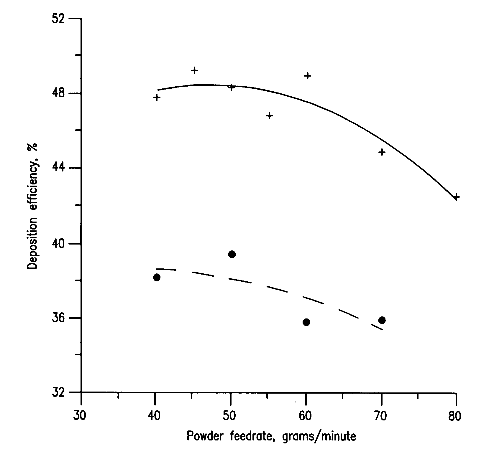
[0082]This example was conducted with a Praxair model 1108 plasma torch, although parameters could be found for making the desired coating with other torches, such as with the Praxair detonation gun or Praxair super detonation gun, the latter being of even higher particle velocity and temperature. In the Praxair model 1108 plasma torch, the plasma is developed in a flow of argon plus hydrogen gas by an electrical arc discharged between an electrode and an anode. The powder is carried in another argon stream and injected upstream of the arc, benefiting from a full transmit though the arc zone. These flows and electrical currents can be varied to determine their effects on coating deposition rates.

[0083]Table C shows the powders used in this coating deposition. Powder C is significantly more pure than Powder D in the unwanted impurities of alumina, silica, iron oxide, titania, calcia, magnesia and other oxides.

TABLE CPowder Compositions(Weight percent)Powder DPowder CZirconiaBalanceBa...

example 3

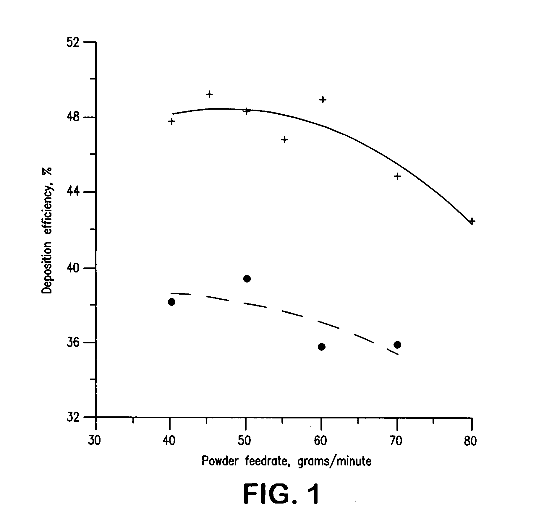
[0087]Different torch gas flow and power conditions were evaluated. In a designed experiment, total gas flows of 176 to 264 cubic feet per hour and torch currents of 160 to 190 amperes (the KW of energy varied from 11.7 to 14.8) were tested. It was found that reducing the total gas flows to 176 cubic feet per hour at 14.3 KW gave the highest deposition efficiency, and this was 10 efficiency points higher than shown on FIG. 1 for Powder C. It is believed that these conditions obtain higher melting fractions of the powder by slowing the particles down somewhat as they transmit the arc zone and by increasing the available enthalpy for melting. It may not be quite that simple since the highest KW or enthalpy condition did not giver the highest deposition efficiency. Multiple correlation analysis of the deposition efficiency results show an expected increase with torch current and a decrease with increasing total gas flow, but also a possible interaction between the two variables.

[0088]T...


PUM

PropertyMeasurementUnit
Temperatureaaaaaaaaaa

Abstract

This invention relates to blades for a gas turbine engine, said blades having an inner end adapted for mounting on a hub and a blade tip located opposite the inner end, and wherein at least a portion of the blade tip is coated with a thermally sprayed coating of a high purity yttria or ytterbia stabilized zirconia powder, said thermally sprayed coating having a density greater than 88% of the theoretical density with a plurality of vertical macrocracks substantially homogeneously dispersed throughout the coating in which a cross-sectional area of the coating normal to the blade tip exposes a plurality of vertical macrocracks extending at least half the coating thickness in length up to the full thickness of the coating and having from about 5 to about 200 vertical macrocracks per linear inch measured in a line parallel to the surface of the blade tip and in a plane perpendicular to the surface of the blade tip, and said high purity yttria or ytterbia stabilized zirconia powder comprising from about 0 to about 0.15 weight percent impurity oxides, from about 0 to about 2 weight percent hafnium oxide (hafnia), from about 6 to about 25 weight percent yttrium oxide (yttria) or from about 10 to about 36 weight percent ytterbium oxide (ytterbia), and the balance zirconium oxide (zirconia).

Description

RELATED APPLICATIONS[0001]This application claims the benefit of U.S. Provisional Application Ser. No. 60 / 808,530, filed on May 26, 2006, and U.S. Provisional Application Ser. No. 60 / 861,438, filed on Nov. 29, 2006, both of which are incorporated herein by reference. This application is related to U.S. patent application Ser. No. (21607-1), filed on an even date herewith; U.S. patent application Ser. No. (21607-3), filed on an even date herewith; U.S. patent application Ser. No. (21607-4), filed on an even date herewith; U.S. patent application Ser. No. (21607-5), filed on an even date herewith; and U.S. patent application Ser. No. (21607-6), filed on an even date herewith; all of which are incorporated herein by reference.FIELD OF THE INVENTION[0002]The invention relates to blades, such as turbine and compressor blades for gas turbines, in which the tips of the blades are coated with a thermally sprayed coating made from high purity yttria or ytterbia stabilized zirconia powder.BAC...

Claims


Application Information

Patent Timeline
IPC IPC(8): F03B3/12
CPCC23C4/02C23C4/105F01D5/288Y02T50/67Y02T50/672F05D2300/15C23C28/345C23C28/3455C23C28/347C23C28/36C23C28/3215C23C4/11Y02T50/60
Inventor TAYLOR, THOMAS ALANAPPLEBY, DANNY LEEFEUERSTEIN, ALBERTBOLCAVAGE, ANNHITCHMAN, NEIL
Owner PRAXAIR ST TECH INC
Why Eureka
Try Eureka