
RF coil assembly for magnetic resonance imaging and spectroscopy systems

a magnetic resonance imaging and spectroscopy technology, applied in the field of nuclear magnetic resonance imaging (mri) methods and systems, can solve the problems of interference patterns inside the body, bsub>1 /sub>(rf) field inhomogeneity induced, and problems that are difficult to tune, etc., to achieve convenient portability, easy and inexpensive construction, and easy to tune

Active Publication Date: 2007-12-06
WISCONSIN ALUMNI RES FOUND
View PDF42 Cites 61 Cited by
  • Summary
  • Abstract
  • Description
  • Claims
  • Application Information

AI Technical Summary

Benefits of technology

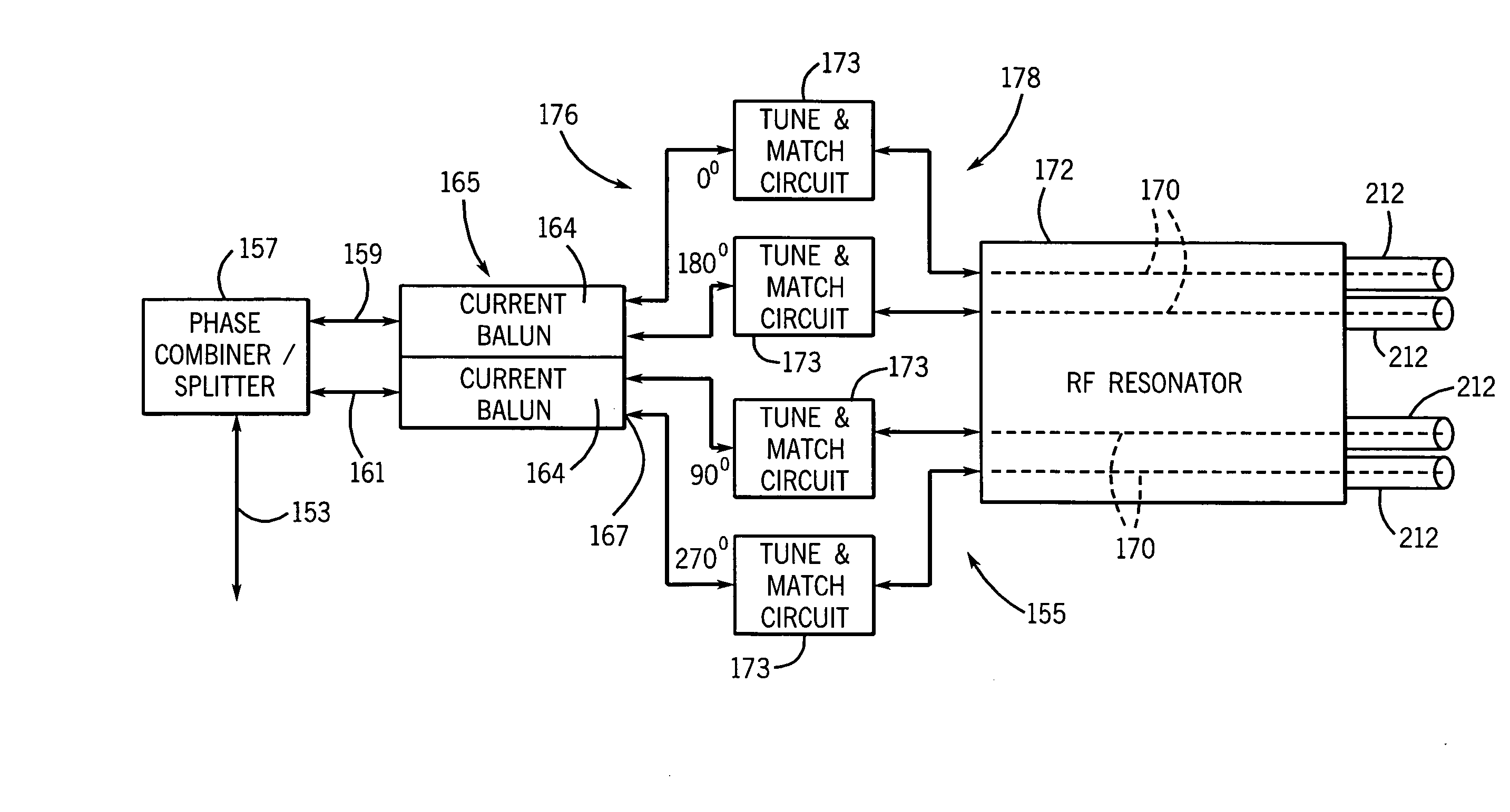
[0015] The present invention is a TEM coil with drive circuitry which may be used as a whole body RF coil on an MRI system or used as a local coil with an MRI system to transmit a uniform B1 magnetic field or receive NMR signals. Unlike the TEM volume resonator described by Vaughan in U.S. Pat. No. 5,557,247, the TEM coil or resonator of the present invention is more of a “pure” TEM device in that the utility volume itself is not a resonant structure, and multiport excitation via a plurality of phased current baluns (as described below) suppresses unwanted modes, such that only excitation equivalent to the M=1 mode described in the Vaughan patent is possible.
[0020] Another aspect of the invention is a coil assembly that can operate at multiple Larmor frequencies simultaneously. This multi-nuclear capability is possible by providing multiple resonators having separate pairs of conductive legs within the same cylindrical shield and enclosing the same imaging volume. Separate drive circuits are provided for the separate pairs of conductive legs that are operated at different Larmor frequencies. The terminal susceptance elements associated with a pair of conductive legs are optimized for the Larmor frequency of one nucleus while also effecting a voltage antinode, or high impedance at the Larmor frequency of the other nucleus. Thus, in selected cases of dual nuclear capability, the two channels can be well isolated from each other.
[0022] The coil assembly is well suited for operation at high polarizing magnetic field strengths (B0), e.g. 3 T or above, with easy portability between different magnetic field strengths. The coil assembly can be easily and inexpensively constructed, is easy to tune, and provides good B1 field homogeneity, good stability with varying loads, high transmit efficiency, and a high receive signal to noise ratio (SNR).

Problems solved by technology

High field MRI offers many benefits, while simultaneously presenting many research and design problems.
The main problem with high field imaging is B1 (RF) field inhomogeneity induced by the sample under examination.
Due to the multiple sources of B1 field in a coil (multiple conductors), these phase shifts result in interference patterns inside the body.
As one increases the static magnetic field above and beyond 3 T, this problem worsens.
As a result, stray or “parasitic” capacitance is created between the load and the conductive elements of the RF coil.
It follows that an asymmetric load placed in the coil would lead to unequal frequency shifts in the resonant loops of the coil, thereby perturbing the ideal sinusoidal current distribution and eliminating the desired “neutral point” in the center of the coil, leading to poor B1 field homogeneity.
In addition, local E field “hot spots” may occur, which may cause excessive RF heating above the specific limits on specific absorption rates (SAR) for human tissue set by the FDA.
As indicated above, the birdcage coil is difficult to tune at more than one Larmor frequency and the substantial change in Larmor frequency required to examine these alternative spin species is not practical.
An important limitation of prior multinuclear coils is that they consist of multi-modal resonant structures such as birdcage or TEM volume resonators.
In addition, poor isolation tends to degrade efficiency for each component of the coil in question.
During the time interval between scans, subject motion may occur, making the co-registration of the two scans difficult.

Method used


Image

  • RF coil assembly for magnetic resonance imaging and spectroscopy systems
  • RF coil assembly for magnetic resonance imaging and spectroscopy systems
  • RF coil assembly for magnetic resonance imaging and spectroscopy systems

Examples


Embodiment Construction

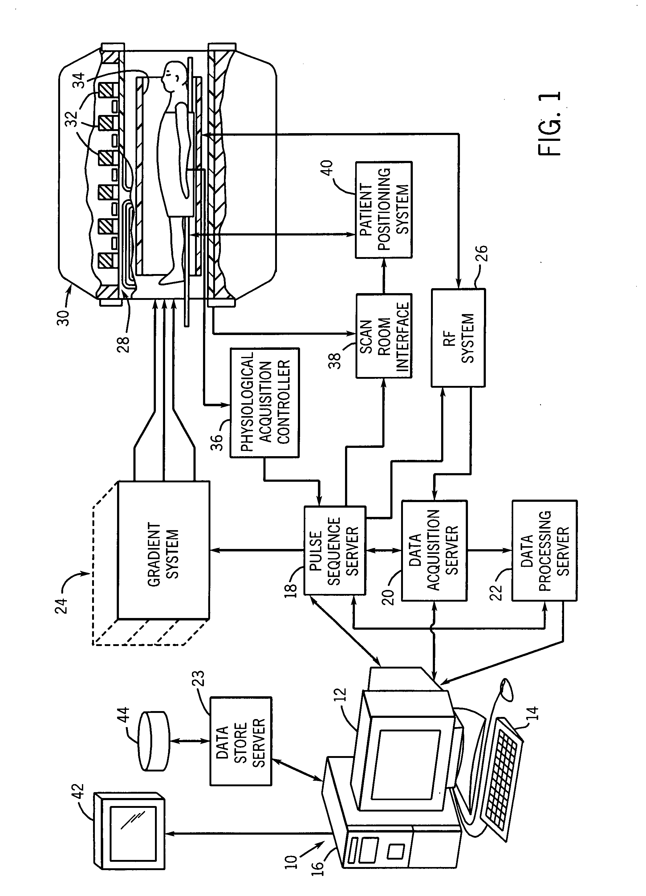
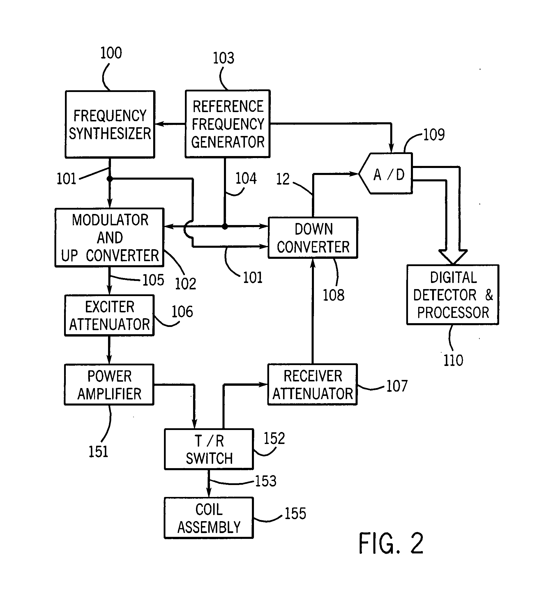
[0042] Referring particularly to FIG. 1, the preferred embodiment of the invention is employed in an MRI system. The MRI system includes a workstation 10 having a display 12 and a keyboard 14. The workstation 10 includes a processor 16 which is a commercially available programmable machine running a commercially available operating system. The workstation 10 provides the operator interface which enables scan prescriptions to be entered into the MRI system.

[0043] The workstation 10 is coupled to four servers: a pulse sequence server 18; a data acquisition server 20; a data processing server 22, and a data store server 23. In the preferred embodiment the data store server 23 is performed by the workstation processor 16 and associated disc drive interface circuitry. The remaining three servers 18, 20 and 22 are performed by separate processors mounted in a single enclosure and interconnected using a 64-bit backplane bus. The pulse sequence server 18 employs a commercially available mi...


PUM


Abstract

An RF coil assembly for an MRI system includes a resonator formed by a cylindrical shield and pairs of opposing conductive legs disposed symmetrically around a central axis and extending the axial length of the shield. Drive circuitry for each pair of opposing conductive legs includes a current balun that maintains substantially equal and opposite currents in the two conductive legs. Terminal susceptance elements are used to maintain maximum currents and minimum voltage at the midpoints of the conductive legs. Multinuclear measurements can be made simultaneously at different Larmor frequencies.

Description

CROSS REFERENCE TO RELATED APPLICATIONS [0001] This application claims the benefit of U.S. Provisional Patent Application Ser. No. 60 / 793,283, filed Apr. 19, 2006, and titled “RF Coil for Magnetic Resonance Imaging and Spectroscopy Systems”, which is hereby incorporated by reference.STATEMENT REGARDING FEDERALLY FUNDED RESEARCH [0002] This invention was made with United States government support awarded by the following agency: NIH grants: HL069116 and HL066488. The United States has certain rights in this invention.FIELD OF THE INVENTION [0003] The field of the invention is nuclear magnetic resonance imaging (MRI) methods and systems. More particularly, the invention relates to coils used to apply radio frequency (RF) magnetic fields to the subject being examined and coils used to receive NMR signals produced in response. BACKGROUND OF THE INVENTION [0004] When a substance such as human tissue is subjected to a uniform magnetic field (polarizing field B0) applied along the z axis o...

Claims


Application Information

Patent Timeline
IPC IPC(8): G01R33/34
CPCG01R33/345G01R33/3453G01R33/3635G01R33/5659G01R33/3678G01R33/3685G01R33/422G01R33/365
Inventor ERICKSON, MATTHEW G.FAIN, SEAN B.KURPAD, KRISHNA N.HOLMES, JAMES H.GRIST, THOMAS M.
Owner WISCONSIN ALUMNI RES FOUND
Learn More