Fluorescence analyzing method, fluorescence analyzing apparatus and image detecting method

a fluorescence analysis and image detection technology, applied in the field of image detection methods, can solve the problems of increasing system costs, affecting the detection speed, and requiring expensive two-dimensional sensors, so as to reduce the number of pixels required, and improve the detection speed.

Active Publication Date: 2007-12-06
HITACHI HIGH-TECH CORP
View PDF2 Cites 3 Cited by
  • Summary
  • Abstract
  • Description
  • Claims
  • Application Information

AI Technical Summary

Benefits of technology

[0018]The present invention makes it possible to reduce the number of pixels required for the two-dimensional sensor without impairing the accuracy in measurement. For example, the number of pixels can be reduced from several hundred times the number of regions to be measured to which oligonucleotide is fixed, to thirty or less times the number of regions, or further to ten or less times the number of regions. Thus, measurement can be performed efficiently. Accordingly, in a case where the same two-dimensional sensor is used, fluorescent images can be concurrently obtained from a larger number of regions, and thereby high throughput can be achieved. In a case where a camera having a small number of pixels is used, measurement can be performed more inexpensively.
[0019]For example, for the same number of molecules to be measured, the present invention allows efficient detection with a small number of pixels, and hence makes it possible to reduce the price of the two-dimensional sensor. Moreover, optical resolution can be made substantially equivalent to each interval between the regions to which oligonucleotide is fixed. Thus, a condenser lens with a large numerical aperture does not need to be used, and a low-priced lens can be used. In addition, it is not necessary to use an immersion lens, and thus the operation can be made easier.

Problems solved by technology

For this reason, the optical system has a problem that detection speed slows down, and that an expensive two-dimensional sensor is required.
Moreover, since fluorescent images need to be detected with a higher resolving power, there is another problem with increased costs for the system in which a condenser lens with a large numerical aperture (NA) needs to be used.

Method used


Image

  • Fluorescence analyzing method, fluorescence analyzing apparatus and image detecting method
  • Fluorescence analyzing method, fluorescence analyzing apparatus and image detecting method
  • Fluorescence analyzing method, fluorescence analyzing apparatus and image detecting method

Examples


first embodiment

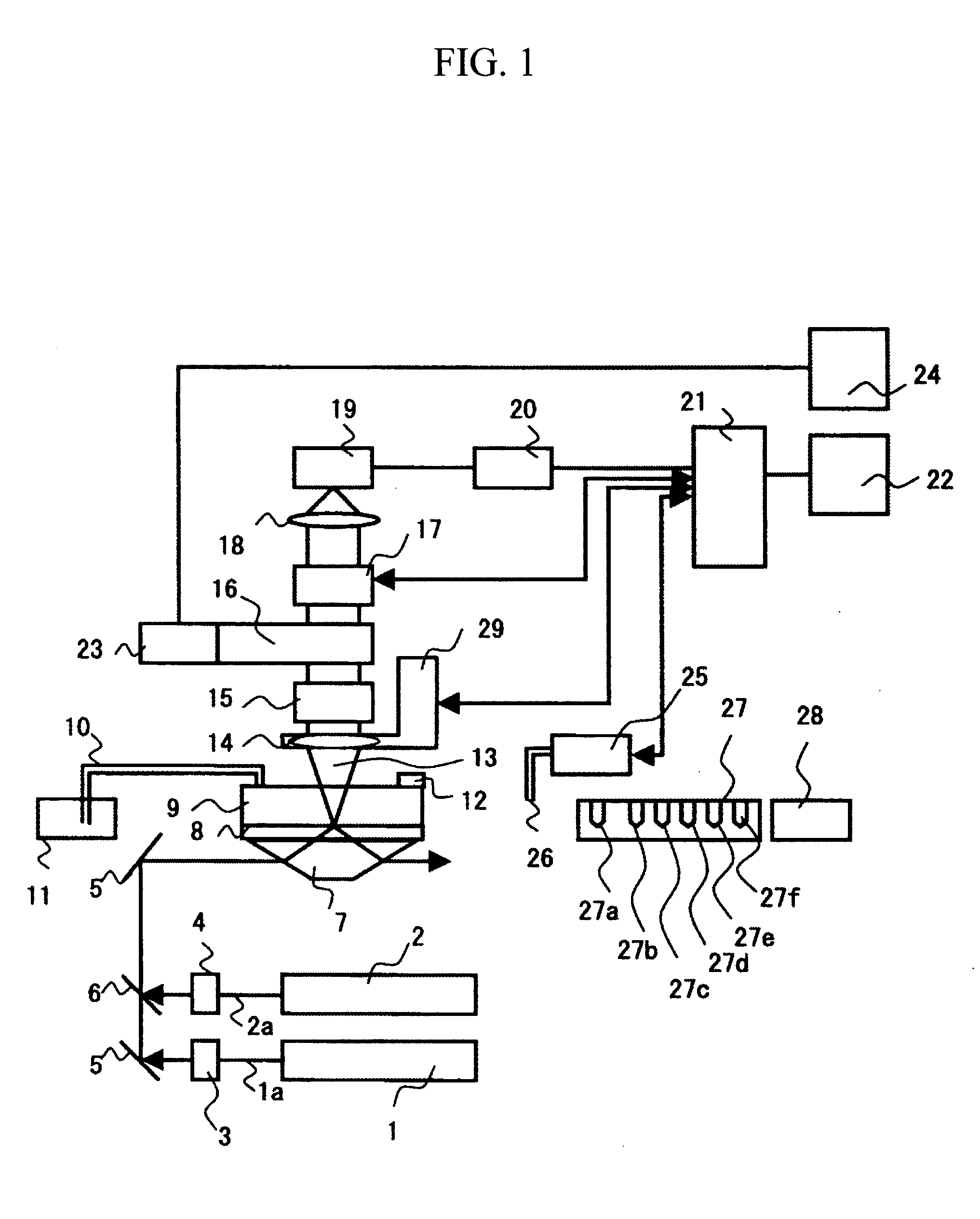
[0027]A description will be given of an apparatus and a method for sequencing fragments of sample DNA by equidistantly trapping, molecule by molecule, fragments of the sample DNA to be analyzed on a surface of a board; inducing extension for substantially every base; and then detecting, for one molecule at a time, captured fluorescence labels. Specifically, the apparatus and the method are used to perform sequencing of the sample DNA by repeating a cycle including the steps of: inducing a DNA polymerase reaction by using four types of dNTP derivatives with detectable labels, which are captured as substrates of DNA polymerase in template DNA, and which can terminate a DNA chain extension reaction, with the presence of a protecting group; then detecting the captured dNTP derivatives on the basis of fluorescence or the like; and then returning the dNTP derivatives to an extension-capable state. Incidentally, since the above operation is based on a method of single molecule fluorescence...

second embodiment

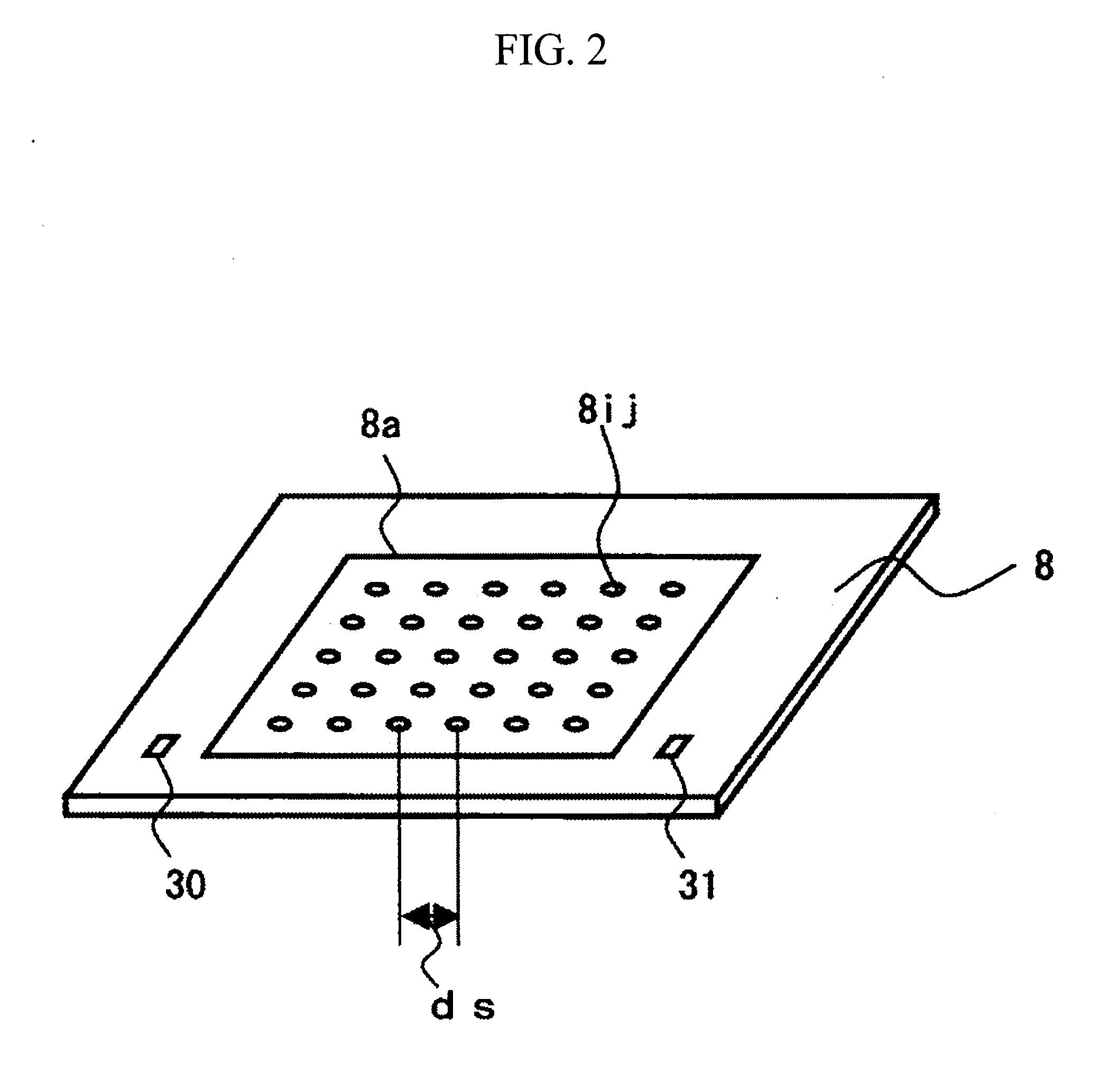
[0047]The apparatus according to the first embodiment is configured so that each single DNA molecule individually enters the region 8ij. However, the apparatus may be configured so that groups 51 of DNA molecules are spaced apart at regular intervals on a board 50, as shown in FIG. 5. In this case, plural molecules of the same DNA fragments are captured in each of the region 8ij. The base extension reaction needs almost all molecules to be extended similarly. Therefore, the measurement needs enough reactive time. In the second embodiment, the plural molecules exist in each of the region 8ij. Therefore, because fluorescent strength grows, it becomes easy to detect. Moreover, even if the reaction of some molecules doesn't proceed when tens of thousands of molecules are fixed to each of the region 8ij, the influence of the sequencing on accuracy is a little. Therefore, the system can be composed at a low cost.

third embodiment

[0048]Description will be given of an embodiment using another form of reaction region. FIG. 6 shows the structure of a board 60 according to the third embodiment. The board 60 has a structure including a reaction region 60a, plural regions 60ij which are formed in the reaction region 60a, and in which DNA is fixed, and an optically opaque mask 60b formed around the plural regions 60ij. Metal, such as aluminum or chromium, silicon carbide or the like, can be employed for a material of the mask. The material is formed into a thin film by vapor deposition or the like. Each region 60ij has a diameter of 100 nm or less. Methods for forming this opening in the mask 60b include vapor deposition using projection method (with which an appropriate mask is disposed between a deposition source and the board, to be subjected to vapor deposition), electron beam lithography and direct writing using photolithography.

[0049]The third embodiment makes it possible to achieve the same effects as those ...


PUM

PropertyMeasurementUnit
diameteraaaaaaaaaa
fluorescence analyzingaaaaaaaaaa
fluorescence measurementaaaaaaaaaa

Abstract

A fluorescence analyzing method includes the steps of irradiating a board, to which oligonucleotide is fixed, with light for fluorescence measurement; focusing produced fluorescence to form an image; and detecting the fluorescence with a two-dimensional sensor. Here, the board is provided with plural regions to which the oligonucleotide is fixed, and the plural regions are spaced apart from one another on the board substantially equidistantly in the vertical and horizontal directions. A fluorescent image is detected in a condition where the following equation is satisfied:
dd=ds×M/n
where ds denotes the interval between the regions, M denotes the imaging magnification of an optical focusing/imaging system, dd denotes the pixel pitch of the two-dimensional sensor, and n denotes an integer (n=1, 2, 3, 4, 5).

Description

BACKGROUND OF THE INVENTION[0001]1. Field of the Invention[0002]The present invention relates to an image detecting method. For example, the present invention relates to a method and an apparatus which capture fluorescence-labeled oligonucleotide in plural positions on a plane, and which then detect a fluorescence intensity and a fluorescence pattern on the basis of the captured oligonucleotide.[0003]2. Description of the Related Art[0004]The techniques of analyzing DNA, RNA, protein and so on are important in the fields of medicine, biology and the like, including gene analysis and gene diagnosis. Particularly in recent years, attention has been given to a method and an apparatus for simultaneously examining and analyzing various types of DNA sequence information and genetic information from one analyte, by using a DNA microarray (also defined as various names, such as an oligochip, a DNA chip and a biochip, which will be hereinafter collectively called a “DNA microarray”). The DNA...

Claims


Application Information

Patent Timeline
Patent Type & Authority Applications(United States)
IPC IPC(8): C12Q1/68G06F19/00C12M3/00C12M1/00G01N21/64G01N21/78
CPCG01N21/6452
Inventor TAKAHASHI, SATOSHIIRIE, TAKASHI
Owner HITACHI HIGH-TECH CORP
Why Eureka
Try Eureka