
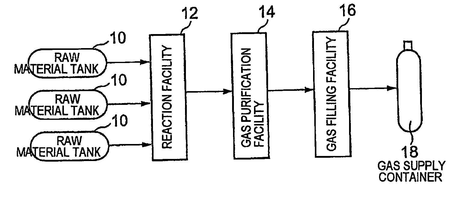
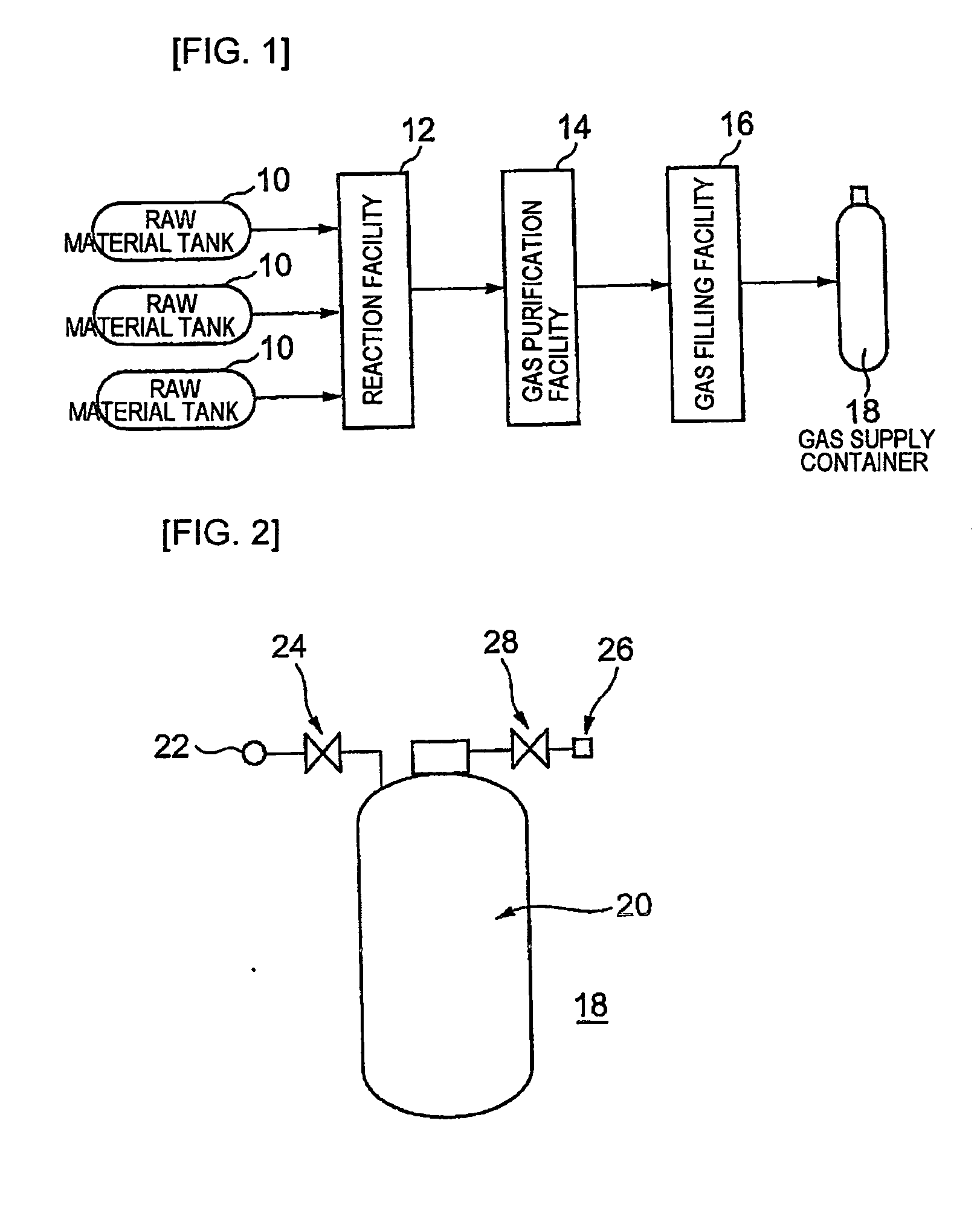
Gas Production Facility, Gas Supply Container, And Gas For Manufacture Of Electronic Devices

a technology for electronic devices and production facilities, which is applied in the direction of mechanical equipment, solid-state diffusion coatings, organic chemistry, etc., can solve the problem that the current impurity management of raw materials for the manufacture of semiconductor devices cannot be said to be sufficient, and achieve the effect of high purification of an electronic devi

Inactive Publication Date: 2007-12-06
ZEON CORP
View PDF3 Cites 7 Cited by
  • Summary
  • Abstract
  • Description
  • Claims
  • Application Information

AI Technical Summary

Benefits of technology

[0013] An object of this invention is to provide an electronic device manufacturing gas production facility and a supply container that can reduce incorporation of impurities such as moisture in the state of a feed gas and decomposition / dissociation of the feed gas and thus is sufficiently effective for achieving higher performance / higher reliability of a semiconductor device, an electronic device manufacturing gas production method, and an electronic device manufacturing gas.
[0015] As a result of conducting diligent studies in order to accomplish the foregoing objects, the present inventors have found that the roughness and material of the inner surfaces of a feed gas production facility and supply facility largely affect the impurity content of a feed gas and setting them in proper ranges is effective for realizing high purification of a fluorinated carbon compound for use in carrying out the processing that uses a plasma, and have reached the completion of this invention.
[0023] According to this invention, there are obtained a production method and a supply method each being sufficiently effective for high purification of an electronic device manufacturing feed gas, particularly a fluorinated carbon compound.

Problems solved by technology

However, there has been a problem that the current impurity management of the raw materials for the manufacture of semiconductor devices cannot be said to be sufficient.

Method used


Image

  • Gas Production Facility, Gas Supply Container, And Gas For Manufacture Of Electronic Devices
  • Gas Production Facility, Gas Supply Container, And Gas For Manufacture Of Electronic Devices
  • Gas Production Facility, Gas Supply Container, And Gas For Manufacture Of Electronic Devices

Examples


example 1

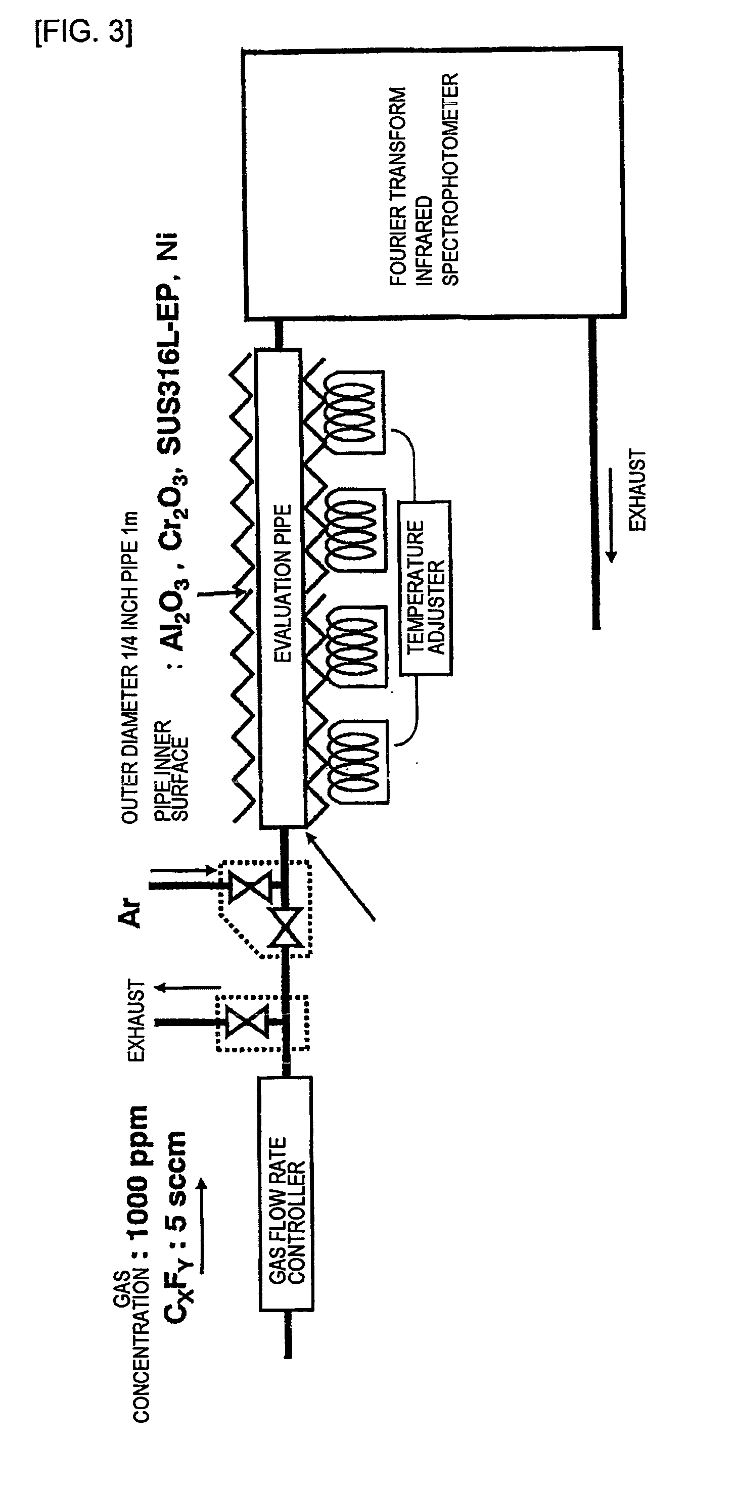
[0099] In this Example 1, a ferritic stainless steel pipe (commercial product) having a Cr content of 29.1 wt % was electrolytically polished on its inner surface and used. The outer diameter of the pipe was ¼ inches, the length of the pipe was 1 m, and the surface roughness was 0.5 μm in terms of a center line average roughness Ra. After the electrolytic polishing, the foregoing stainless steel was charged into a furnace and the temperature was raised from room temperature to 550° C. in 1 hour while causing an Ar gas having an impurity concentration of several vol ppb or less to flow in the furnace, and then baking was carried out at that temperature for 1 hour to remove adhering moisture from the surface. After the baking was finished, the gas was switched to an oxidizing gas having a hydrogen concentration of 10% and a moisture concentration of 100 vol ppm and heat treatment was carried out for 3 hours. Part of the foregoing pipe was cut out and it was confirmed by XPS analysis t...

example 2

[0100] In this Example 2, an austenitic stainless steel pipe (commercial product) having an Al content of 4.0 wt % was electrolytically polished on its inner surface and used. The pipe having the same size and the same surface roughness as those in Example 1 was used. After the electrolytic polishing, the foregoing stainless steel was charged into a furnace and the temperature was raised from room temperature to 400° C. in 1 hour while causing an Ar gas having an impurity concentration of several vol ppb or less to flow in the furnace, and then baking was carried out at that temperature for 1 hour to remove adhering moisture from the surface. After the baking was finished, the gas was switched to an oxidizing gas having a moisture concentration of 5 vol ppm and further added with 10 vol % of hydrogen in the moisture mixed gas and oxidation treatment was carried out at a treatment temperature of 900° C. for a treatment time of 1 hour. Part of the foregoing pipe was cut out and it was...

example 3

[0107] After the inner surface of a bomb (commercial product) with a capacity of 1 liter made of a ferritic stainless steel having a Cr content of 29.1 wt % was electrochemically polished (Ra=0.5 μm), the foregoing bomb was charged into a furnace and the temperature was raised from room temperature to 550° C. in 1 hour while causing an Ar gas having an impurity concentration of several ppb or less to flow in the furnace, and then baking was carried out at that temperature for 1 hour to remove adhering moisture from the surface. After the baking was finished, the gas was switched to an oxidizing gas having a hydrogen concentration of 10 vol % and a moisture concentration of 100 vol ppm and heat treatment was carried out for 3 hours.


PUM

PropertyMeasurementUnit
roughnessaaaaaaaaaa
roughness Raaaaaaaaaaa

Abstract

An apparatus for producing a gas using a raw material gas having high reactivity, in particular, a fluorinated hydrocarbon, or a vessel for supplying the gas, characterized in that the surface of a portion thereof contacting with the gas has an average roughness of 1 μm or less in terms of a center line average roughness Ra. It is preferred that an oxide-based passivated film such as a film based on chromium oxide, aluminum oxide, yttrium oxide, magnesium oxide or the like is formed on the surface having a roughness controlled as above. The above apparatus and vessel can be suitably used for preventing the contamination of a raw material gas originated from a gas production apparatus or a vessel for supplying the gas.

Description

TECHNICAL FIELD [0001] This invention relates to a gas production facility, a gas supply container, and an electronic device manufacturing gas that are useful in the field of manufacturing electronic devices. More specifically, this invention relates to a facility from a final production process to filling into a container of a gas (also including a liquefied gas) for use in carrying out the processing that uses a plasma, a supply container and a gas for plasma reaction. BACKGROUND ART [0002] In recent years, following the increase in level and performance of electronic devices, high-purification production techniques for raw materials to be used have been getting important. Particularly, in the manufacture of semiconductor devices, the ppb (parts per billion) level impurity management has been required for raw materials to be used. [0003] However, there has been a problem that the current impurity management of the raw materials for the manufacture of semiconductor devices cannot b...

Claims


Application Information

Patent Timeline
Patent Type & Authority Applications(United States)
IPC IPC(8): C07C19/08A61L9/00C23C4/10C23C8/02C23C8/16C23C8/18C23C30/00F17C1/10
CPCC23C4/105F17C1/10C23C30/00C23C8/02C23C4/11C23C8/16C23C8/18C23C4/10
Inventor OHMISHIRAI, YASUYUKIKATO, TAKEYOSHITANAKA, KIMIAKINAKAMURA, MASAHIROTANAKA, KATSUTOMO
Owner ZEON CORP
Learn More