Oxidative cleaning method and apparatus for electron microscopes using UV excitation in a oxygen radical source

a technology of oxygen radical source and electron microscope, which is applied in the direction of instruments, heat measurement, machines/engines, etc., can solve the problems of affecting the accuracy of analysis, affecting the scanning area, or losing resolution,

Inactive Publication Date: 2007-12-13
VANE RONALD A
View PDF32 Cites 24 Cited by
  • Summary
  • Abstract
  • Description
  • Claims
  • Application Information

AI Technical Summary

Benefits of technology

[0014]An improved method and apparatus for oxidative cleaning the specimen chamber, the specimen, and the specimen stage of electron microscopes and other charged beam instruments are disclosed. The invention covers the use of a UV light lamp with UV wavelengths below 193 nm, that disassociates oxygen, with an oxygen containing gas flowing past the UV lamp to form an Oxygen radical source that may be mounted on a port of the specimen chamber of the electron microscope. The oxygen radicals flow from the source through the chamber to the pumps and remove hydrocarbons by oxidation. The invention also covers the operation and design of the UV activated oxygen radical source in such a way that allows it to generate oxygen radicals from air and other nitrogen / oxygen mixtures without the production of ions and free electrons. The oxygen radicals are used for cleaning the interior walls and surfaces, specimen stage and specimen. The invention also covers a control method and arrangement for operating the evacuation system of the electron microscope, the UV source, and the admission of gas into the chamber.

Problems solved by technology

Hydrocarbon contaminants adsorbed on the surface or surface films interacting with the incident electron probe beam can distort the results.
The distortion may take the form of deposits of polymer in the scanned area, a darkening of the scanned area, a loss of resolution, or other artifacts.
Deposits created by the interaction of the probe beam with the surface specimen also may interfere with the probe beam or emitted electrons and x-rays and thus adversely affect accurate analysis.
Surfaces are further hydrocarbon contaminated by touching, the use of high vapor pressure materials in vacuum system, or in general “poor vacuum practices”.
Another problem is the condensation of pump oils on the windows of the x-ray and electron detectors distorting results.
The most serious problem of this type is the absorption of low-energy x-rays from Be, C, N, O and F by oil films which can prevent measurement of these elements by X-ray emission spectroscopy.
Once present inside the chamber, these contaminants reside on the chamber surfaces and can be removed only slowly and with low efficiency by the high vacuum pump.
These may be part of the specimen, residues from sample preparation techniques or be caused by improper sample handling or storage techniques.
While the part of the films created in these processes dissipate under vacuum conditions, a small amount generally remains on surfaces and is sufficient to cause problems when the specimen is subsequently examined in the analytical instruments listed.
A disadvantage of ions and electrons from the plasma is that they polymerize the hydrocarbons and make them harder to remove.
Another disadvantage of the Evactron device is that it will not produce O radicals at pressures below 10-4 Torr which keeps the Evactron from cleaning when the instrument is at high vacuum.
Another disadvantage is that the plasma produces high levels of free electrons in SEM imaging while the Evactron plasma is operating.

Method used


Image

  • Oxidative cleaning method and apparatus for electron microscopes using UV excitation in a oxygen radical source
  • Oxidative cleaning method and apparatus for electron microscopes using UV excitation in a oxygen radical source
  • Oxidative cleaning method and apparatus for electron microscopes using UV excitation in a oxygen radical source

Examples


first embodiment

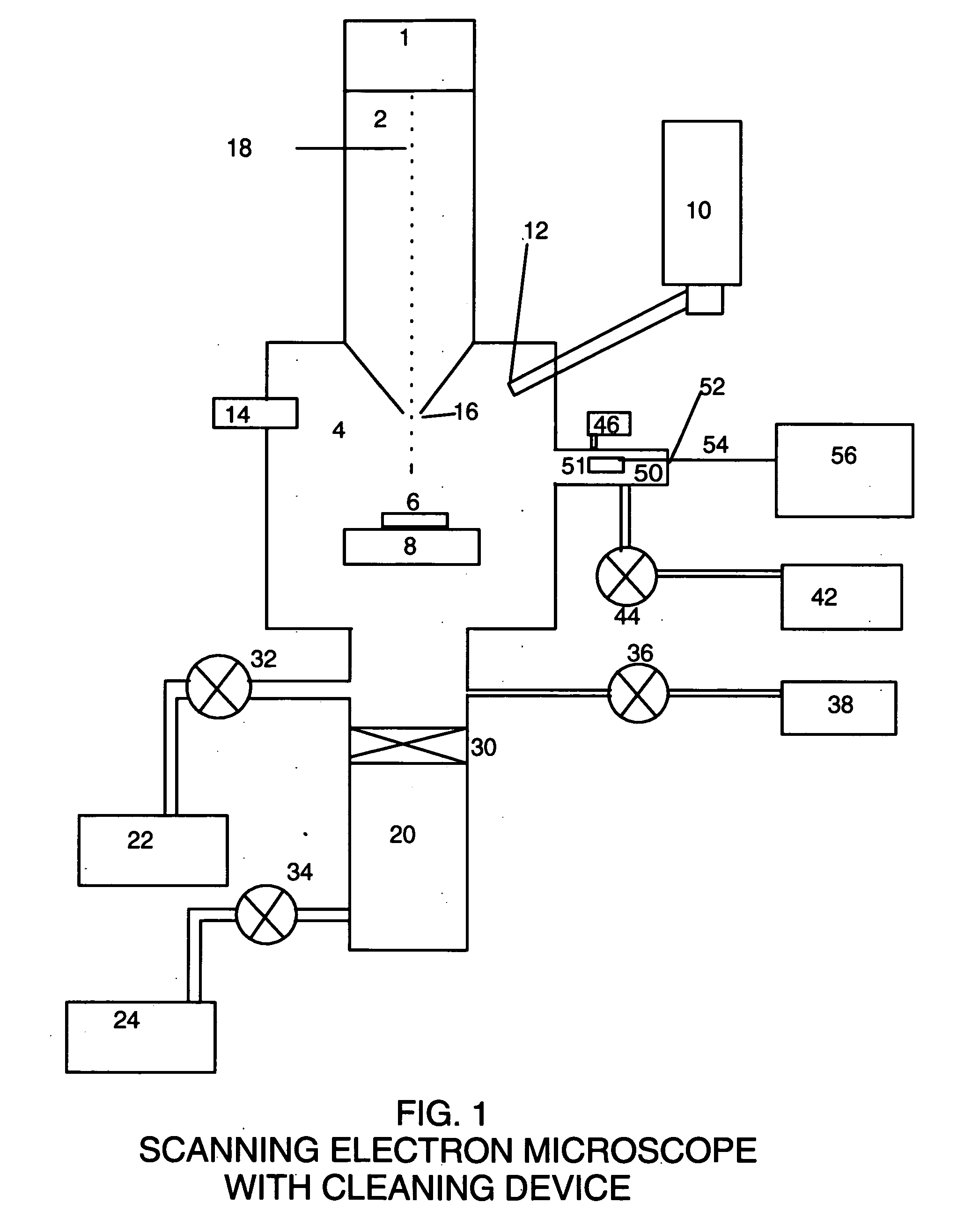
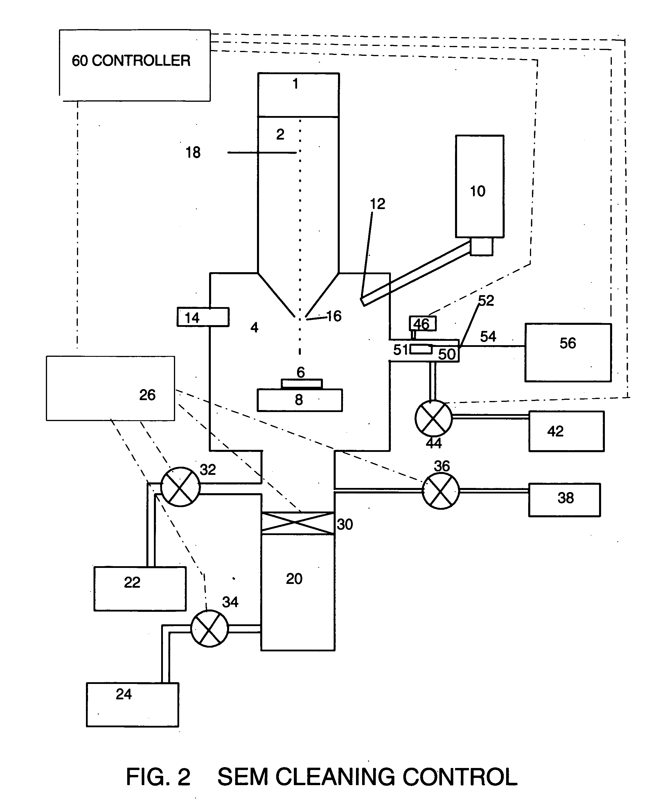
[0049]the present invention method uses a chamber 50 with an interior UV lamp 51. The UV lamp 51 is connected to a power supply 56 through cable 54 and insulated vacuum feedthrough 52 connected to the UV lamp 51. The output of UV lamp power supply 56 controls the power and the temperature of the UV lamp 51. The preferred UV wavelengths are between 193 nm and 150 nm and between 240 nm and 220 nm. At the preferred operating UV wavelengths and pressures of the present method, the Oxygen radicals are produced that flow into the Specimen chamber 4. The UV light may optionally be allowed to enter chamber 4 to activate the hydrocarbons for oxidation. The method of the present invention limits the wavelengths of the UV source so that Nitrogen is not disassociated or ionized, and limits the pressure to below 133 Pa or 1 Torr so that the Oxygen radicals do not react with air molecules to form O3 (Ozone) or N20 molecules by means of three body collisions in significant quantities.

[0050]In the ...

fourth embodiment

[0065]In the invention the UV source is located within the specimen chamber and irradiates said chamber while the Oxygen containing gas flows through the region of the UV source.


PUM


Abstract

An improved method and apparatus are provided for cleaning the specimen and interior specimen chamber of Electron Microscopes, and similar electron beam instruments. The apparatus consists of a UV source oxygen-radical generator placed on a specimen chamber port or inside the specimen chamber under vacuum. Air or other oxygen and nitrogen mixture is admitted to the generator at a pressure below 1 Torr. The UV source radiates UV wavelengths below 190 nm that are used to disassociate oxygen to create the oxygen radicals. The oxygen radicals then disperse by convective flow throughout the chamber to clean hydrocarbons from the surfaces of the chamber, stage and specimen by oxidation to volatile oxide gases. The oxide gases are then removed by the convective flow to the vacuum pump.
In particular it is a novel method and apparatus for cleaning the specimen chamber, specimen stage, and specimen inside the vacuum system of these instruments with oxygen radicals produced from air or other oxygen containing gas by photo-dissociation by passing said gas by a UV source with wavelengths that can produce oxygen radicals. The oxygen radicals are used to oxidize the hydrocarbons and convert them to easily pumped gases. The method and apparatus can be added to the analytical instrument and other vacuum chambers with no change to its analytical purpose or design.

Description

BACKGROUND OF THE INVENTION[0001]1. Field of Invention[0002]The present invention relates to cleaning vacuum chambers and vacuum analytical instruments such as Scanning Electron Microscopes (SEM), Scanning Electron Microprobes, Transmission Electron Microscopes (TEM) and other charge particle beam instruments that are subject to contamination problems from hydrocarbons.[0003]2. Description of Prior Art[0004]Electron microscopy is used to detect, measure, and analyze constituents present in very small areas of materials. Hydrocarbon contaminants adsorbed on the surface or surface films interacting with the incident electron probe beam can distort the results. The distortion may take the form of deposits of polymer in the scanned area, a darkening of the scanned area, a loss of resolution, or other artifacts. Deposits created by the interaction of the probe beam with the surface specimen also may interfere with the probe beam or emitted electrons and x-rays and thus adversely affect a...

Claims


Application Information

Patent Timeline
Patent Type & Authority Applications(United States)
IPC IPC(8): H01J37/16
CPCH01J2237/022H01J37/02
Inventor VANE, RONALD A.
Owner VANE RONALD A
Why Eureka
Try Eureka