Filter for purifying gas mixtures and method for its manufacture

a technology of purifying gas mixture and filter, which is applied in the direction of filtration separation, machine/engine, separation process, etc., can solve the problems of disintegration of soot particles and thus becoming more easily oxidizable, and achieve the effects of increasing the capacity for accumulating soot, improving mutual adhesion of fibers, and reducing the amount of soo

Inactive Publication Date: 2007-12-20
ROBERT BOSCH GMBH
View PDF15 Cites 6 Cited by
  • Summary
  • Abstract
  • Description
  • Claims
  • Application Information

AI Technical Summary

Benefits of technology

[0003] A filter according to the present invention for purifying gas mixtures containing particulates has a porous surface made of filter base material through which the gas mixture to be purified flows. A layer of ceramic fibers is applied to the surface of the filter base material on the side exposed t

Problems solved by technology

This makes the soot particles disintegrat

Method used


Image

  • Filter for purifying gas mixtures and method for its manufacture
  • Filter for purifying gas mixtures and method for its manufacture
  • Filter for purifying gas mixtures and method for its manufacture

Examples


Embodiment Construction

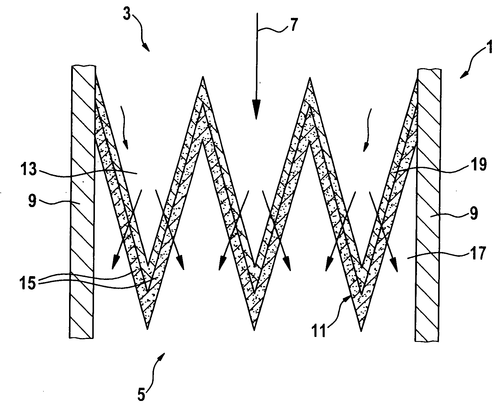
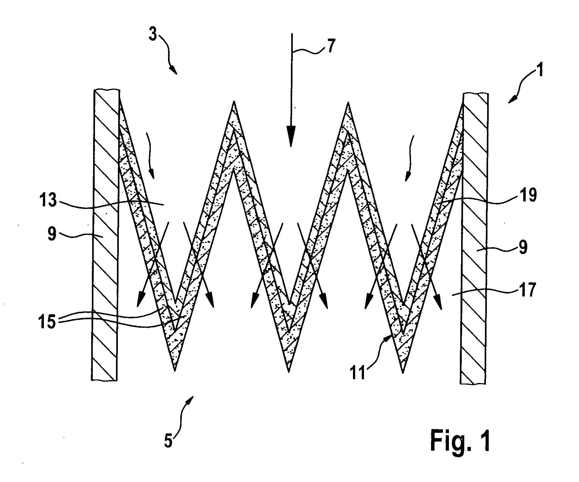
[0020]FIG. 1 shows the schematic structure of a filter for purifying gas mixtures. The filter is, for example, integrated into a system in which a gas mixture containing particulates which are preferably combustible is conducted. The system may be the exhaust gas duct of a Diesel combustion engine, for example. Alternatively, there is also the possibility to situate the filter in a bypass of the exhaust system.

[0021] A filter 1, as shown in FIG. 1, is designed as a stainless steel or sintered metal filter, for example, and has a first side 3 facing the gas mixture to be purified and a second side 5 facing the purified gas mixture. A gas mixture 7 loaded with particles is supplied to filter 1 on its first side 3. Gas mixture 7 loaded with particles is, for example, an exhaust gas stream of a diesel engine, containing soot.

[0022] Filter 1 has a housing 9 into which a filter structure 11 is integrated. Filter structure 11 includes pockets 13, whose ends facing first side 3 are open f...


PUM

PropertyMeasurementUnit
Flow rateaaaaaaaaaa

Abstract

A filter for purifying gas mixtures containing particulates, in particular exhaust gases of internal combustion engines containing soot. The filter has a porous wall made of a filter base material through which the gas mixture to be purified flows. A surface coating of ceramic fibers is applied to the surface of the wall which is exposed to the flow of the gas mixture to be purified. The ceramic fibers are coated with nanoparticles. Furthermore, a method for manufacturing such a filter.

Description

FIELD OF THE INVENTION [0001] The present invention relates to a filter for purifying gas mixtures containing particulates, in particular exhaust gases of internal combustion engines containing soot. The present invention furthermore relates to a method for manufacturing such a filter. BACKGROUND INFORMATION [0002] A device for purifying gas mixtures containing particulates, the device being designed as a filter which has a porous surface made of filter base material exposed to the gas mixture to be purified is known, for example, from German Patent Application No. DE 10 2005 017 265. In this document, a layer of ceramic fibers is applied to the surface of the filter base material exposed to the gas mixture to be purified. The ceramic fibers are conglutinated with the filter base material using a binder. The binder is an inorganic material based on aluminum oxide, silicon oxide, or aluminum silicate, for example. Furthermore, German Patent Application No. DE 10 2005 017 265 describe...

Claims


Application Information

Patent Timeline
IPC IPC(8): B01D46/00
CPCB01D39/2072B01D39/2082B01D46/521B01D46/546B01D53/944B01D2275/10Y02T10/20F01N3/021F01N2330/06F01N2330/10F01N2330/14F01N2410/00F01N2510/065B01D2279/30Y02T10/12
Inventor SCHUMANN, BERNDJOCKEL, JOERGKRUSE, MATTHIAS
Owner ROBERT BOSCH GMBH
Why Eureka
Try Eureka