Side-port sheath for catheter placement and translation

a catheter and side-port technology, applied in the field of side-port sheaths, can solve the problems of large temperature gradients and hot spots, undesirable coagulum and charring of surface tissue, and may be encountered with a large amount of difficulty, so as to reduce the amount of conductive fluid, reduce the formation of undesirable coagulum and charring of surface tissue, and mitigate the effect of electrode-tissue contact problems

Inactive Publication Date: 2007-12-20
ST JUDE MEDICAL ATRIAL FIBRILLATION DIV
View PDF3 Cites 37 Cited by
  • Summary
  • Abstract
  • Description
  • Claims
  • Application Information

AI Technical Summary

Benefits of technology

[0012] It is desirable to be able to treat tissue by forming adequately-deep spot or continuous linear lesions in the tissue while reducing the formation of undesirable coagulum and charring of the surface tissue, while applying a reasonable amount of RF energy, while mitigating electrode-tissue contact problems, and / or while reducing the amount of conductive fluid (e.g., isotonic saline) possibly entering a patient's bloodstream during the procedure. It is also desirable to be able to diagnose tissue using electrical or chemical feedback from the tissue. The side-port sheath of the present invention facilitates improved diagnosis or treatment of tissue.

Problems solved by technology

Several difficulties may be encountered, however, when attempting to form adequately-deep lesions at specific locations using some existing ablation catheters and electrodes.
At the edges of some existing electrodes are regions of very high current density, leading to large temperature gradients and hot spots.
These “edge effects” may result in the formation of undesirable coagulum and charring of the surface tissue.
For example, undesirable coagulum may begin to form when blood reaches around 80° C. for an appreciable length of time, and undesirable tissue charring and desiccation may be seen when tissue reaches around 100° C. for an appreciable length of time.
There two types of undesirable coagulum: coagulum that adheres to and damages the medical device (e.g., the electrode); and coagulum blood clots or curds that may enter a patient's bloodstream, possibly resulting in other health problems for the patient.
Charring of the surface tissue may also have deleterious effects on a patient.
As the temperature of the electrode is increased, the contact time required to form an adequately-deep lesion decreases, but the likelihood of charring surface tissue and forming undesirable coagulum increases.
As the temperature of the electrode is decreased, the contact time required to form an adequately-deep lesion increases, but the likelihood of charring surface tissue and forming undesirable coagulum decreases.
Active temperature control may help, but the placement of thermocouples, for example, is tricky and setting the RF generator for a certain temperature becomes an empirical exercise as actual tissue temperatures are generally different from those recorded next to the electrode due to factors such as convection and catheter design.
Another difficulty encountered with existing ablation electrodes is how to ensure adequate tissue contact.
All of these devices comprise rigid electrodes that do not always conform to the tissue surface, especially when sharp gradients and undulations are present, such as at the ostium of the pulmonary vein in the left atrium and the isthmus of the right atrium.
Consequently, continuous linear lesions are difficult to achieve.
When forming lesions in a heart, the beating of the heart further complicates matters, making it difficult to keep adequate contact between the electrode and the tissue for a sufficient length of time to form a desired lesion.
With a rigid electrode, it can be quite difficult to maintain sufficient contact pressure until an adequate lesion has been formed.
This problem is exacerbated on contoured or trabeculated surfaces.
If the contact between the electrode and the tissue cannot be properly maintained, a quality lesion is unlikely to be formed.
Catheters based upon a virtual electrode may address some of the difficulties, but these catheters often require high flow rates of conductive fluid (e.g., typically around 70 milliliters per minute) to maintain effective cooling for high-power RF applications.
The introduction of a large amount of conductive fluid (used to flush-cool the catheter electrode) into a patient's bloodstream may have detrimental effects on the patient.
Uncontrolled electric field leakage from the circumference of an electrode (e.g., from the outer surface of the electrode) can also be a problem.
This electric field leakage may reduce the efficacy of an ablation device.

Method used


Image

  • Side-port sheath for catheter placement and translation
  • Side-port sheath for catheter placement and translation
  • Side-port sheath for catheter placement and translation

Examples


first embodiment

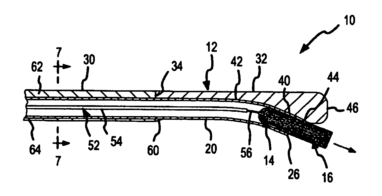
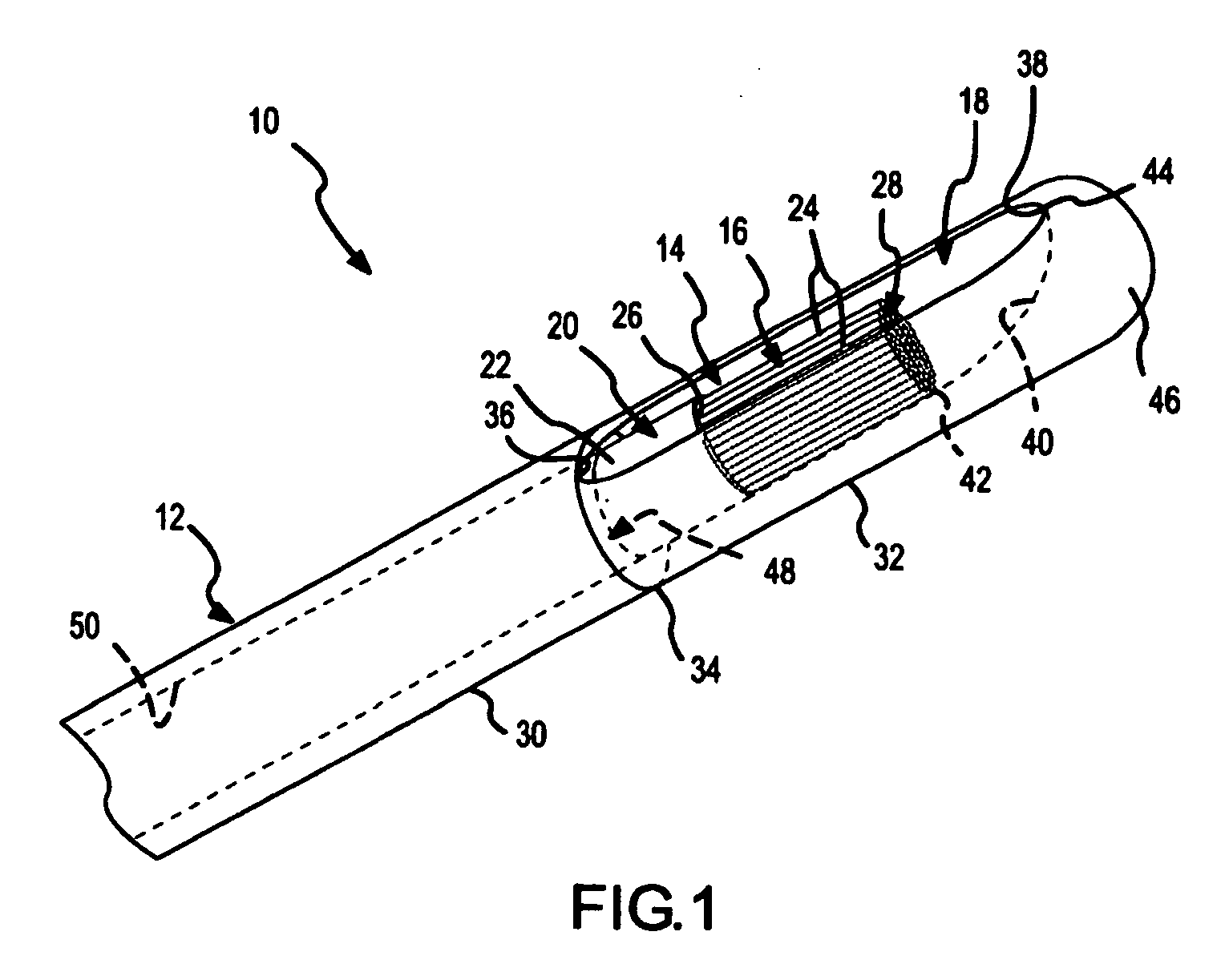
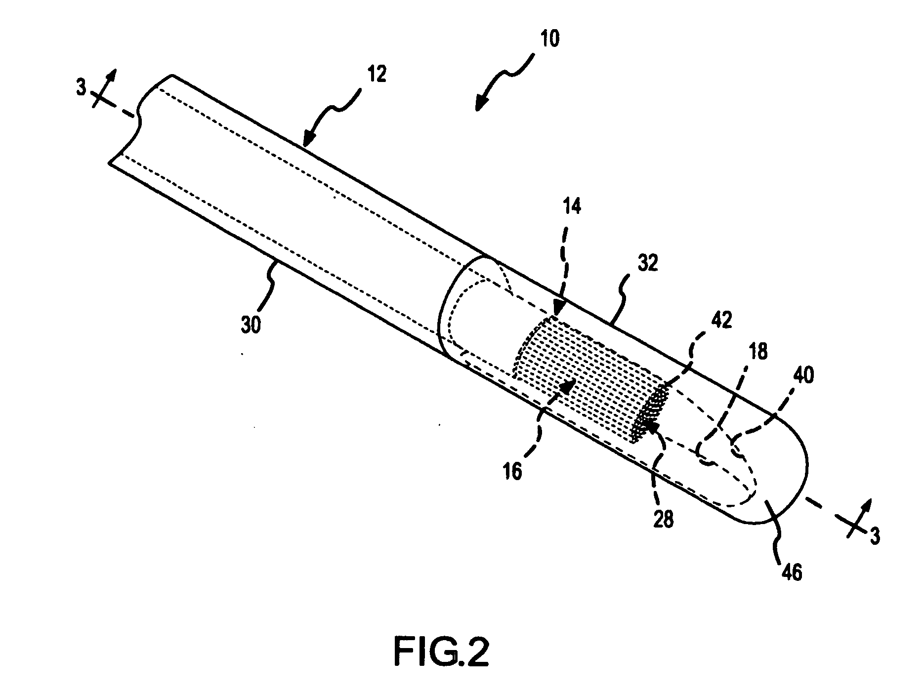
[0046]FIG. 1 is a fragmentary, isometric view of a diagnostic or treatment device 10 comprising a side-port sheath 12 according to the present invention. The side-port sheath 12 is a main or outside catheter that facilitates placement and translation of a gliding or inside catheter 14. As alluded to above, the gliding catheter 14 may be any type of diagnostic or treatment catheter, such as an electrophysiology catheter or an ablation catheter (e.g., a wet-brush or a Livewire.™ catheter available from St. Jude Medical). In FIGS. 1-27, the gliding catheter 14 is depicted as a brush electrode catheter, but, as explained further below in connection with FIGS. 28-32, a variety of different types of gliding catheters could be used with the side-port sheath of the present invention. As a brush electrode catheter, the gliding catheter 14 depicted in FIG. 1 comprises a catheter sheath 20 having an outside surface 22. A brush electrode 16 comprising a plurality of conductive and / or nonconduct...

second embodiment

[0055]FIG. 10 is a fragmentary, isometric view of a diagnostic or treatment device 10′ comprising a side-port sheath 82 according to the present invention. This figure is similar to FIG. 1, but depicts a deflection and suspension ribbon, wire, or strip 84 in phantom alongside an undeployed gliding catheter 14 that is adjacent to the elongated side-port opening 86 in the tip 88 of the side-port sheath 82. The suspension ribbon 84 may comprise, for example, a ribbon of Nitinol or NiTi. As shown to good advantage in FIG. 10, the curved surface 90 that extends from the upper wall 92 of the side-port sheath 82 to a distal edge 94 of the side-port opening 86 is steeper than the gliding surface 40 depicted in, for example, FIGS. 1-3. As explained further below, in this embodiment, the suspension ribbon 84 not only directs the gliding electrode catheter 14 toward the side-port opening 86, but also suspends the electrode 16. Since the suspension ribbon helps push the gliding electrode cathet...


PUM


Abstract

Side-port sheaths for catheter placement and translation are disclosed. The sheaths include a side-port opening through which a gliding catheter may be deployed during diagnosis or treatment of tissue. The side-port sheath may include a suspension ribbon used to deploy, or that aids in the deployment of, the embedded gliding catheter. The suspension ribbon may be slideably or fixably engaged with an outer surface of the sheath of the gliding catheter.

Description

CROSS-REFERENCE TO RELATED APPLICATIONS [0001] This application is a continuation of pending application Ser. No. 10 / 856,145 filed May 27, 2004, the complete disclosure of which is hereby incorporated by reference in their entirety for all purposes.BACKGROUND OF THE INVENTION [0002] a. Field of the Invention [0003] The instant invention is directed toward a device and method for the placement and translation of a catheter in a body cavity. More specifically, it relates to a side-port sheath through which a catheter for diagnosis or treatment of tissue may be placed adjacent to, or in contact with, tissue to be diagnosed or treated. [0004] b. Background Art [0005] It is well known that benefits may be gained by forming lesions in tissue if the depth and location of the lesions being formed can be controlled. In particular, it can be desirable to elevate tissue temperature to around 50° C. until lesions are formed via coagulation necrosis, which changes the electrical properties of th...

Claims


Application Information

Patent Timeline
Patent Type & Authority Applications(United States)
IPC IPC(8): A61B18/08A61B5/04A61B5/042A61B18/14A61N1/05
CPCA61B5/042A61B18/1492A61B2018/1497A61B2018/1475A61B2018/143A61B5/283
Inventor PAUL, SAURAVBELHE, KEDAR RAVINDRACAO, HONGROOP, JOHN AVITHAO, CHOU
Owner ST JUDE MEDICAL ATRIAL FIBRILLATION DIV
Why Eureka
Try Eureka