

Process for the production of electrolyte capacitors
a technology of electrolyte capacitors and electrolyte, which is applied in the manufacture of electrolytic capacitors, electrolytic capacitors, electrolysis components, etc., can solve the problem of low residual current, and achieve the effect of low equivalent series resistance, low residual current, and stable heat dissipation
- Summary
- Abstract
- Description
- Claims
- Application Information
AI Technical Summary
Benefits of technology
Problems solved by technology
Method used
Image

Examples
example 1
[0174] 868 g deionized water and 330 g of an aqueous polystyrenesulfonic acid solution having an average molecular weight of 70,000 and a solids content of 3.8 wt. % were initially introduced into a 2 l three-necked flask with a stirrer and internal thermometer. The reaction temperature was kept between 20 and 25° C. 5.1 g 3,4-ethylenedioxythiophene were added, while stirring. The solution was stirred for 30 minutes. 0.03 g iron(III) sulfate and 9.5 g sodium persulfate were then added and the solution was stirred for a further 24 h.
[0175] After the reaction had ended, to remove inorganic salts 100 ml of a strongly acid cation exchanger and 250 ml of a weakly basic anion exchanger were added and the solution was stirred for a further 2 h. The ion exchanger was filtered off. The poly(3,4-ethylenedioxythiophene) / polystyrenesulfonate dispersion was homogenized ten times with a high pressure homogenizer under a pressure of 700 bar. The dispersion was then concentrated to a solids conten...
example 2
[0179] 5 g dimethylsulfoxide (DMSO) were added to 100 g of dispersion A)-1 from Example 1 and the mixture was stirred to form a dispersion A)-2. One part of this dispersion A)-2 was spin-coated on to a glass microscope slide (26 mm*26 mm*1 mm) by means of a spincoater (Chemat Technology KW-4A) at 1,000 rpm for 5 seconds. The sample was dried at 120° C. for 10 min. Two opposite edges of the microscope slide were then coated with conductive silver. After drying of the conductive silver, the two silver strips were contacted and the surface resistance was determined with a Keithley 199 Multimeter. The layer thickness was determined with a Tencor Alpha Step 500 Surface Profiler. The specific conductivity σ was determined from the surface resistance and layer thickness d from σ=1 / (Rs*d). The layer thickness was 120 nm and the specific conductivity was 483 S / cm.
example 3
[0180] 3.1 Production of Oxidized Electrode Bodies:
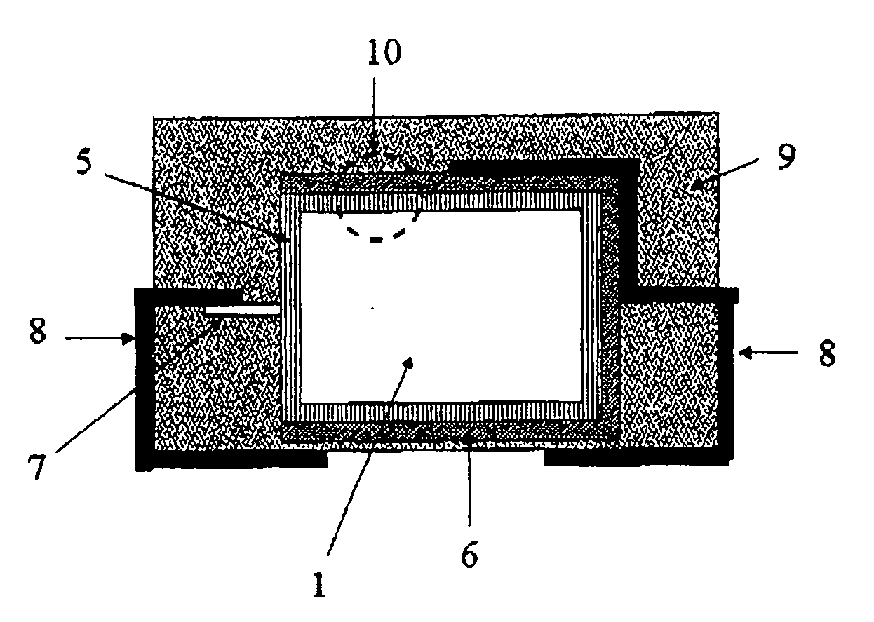
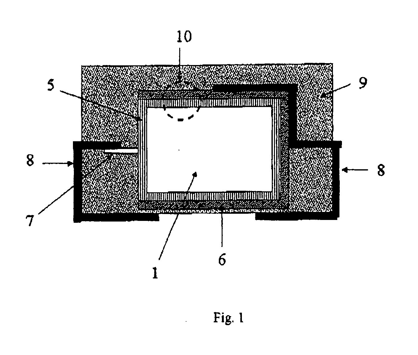
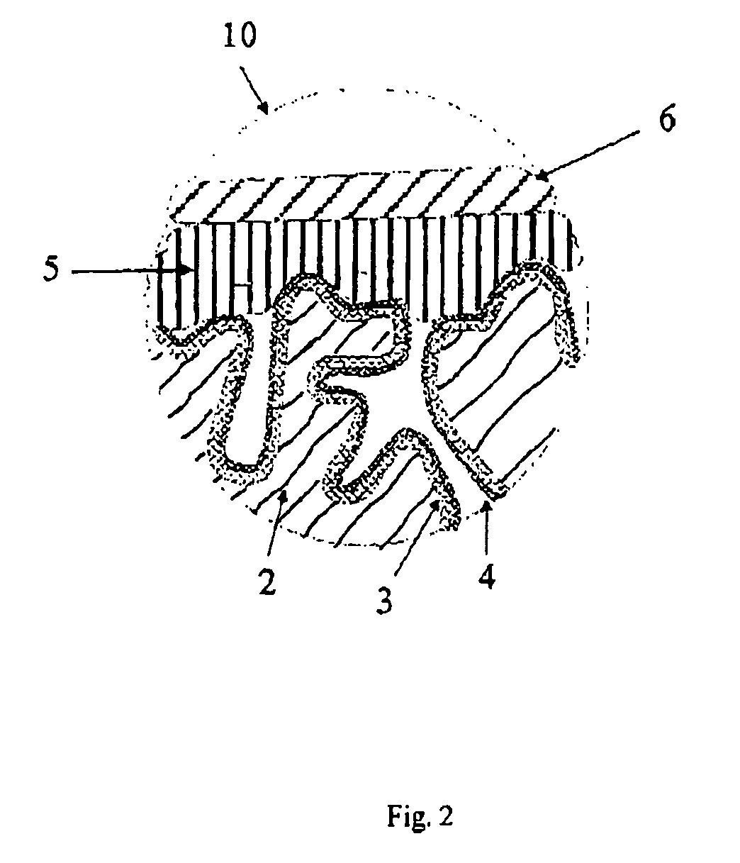
[0181] Tantalum powder having a specific capacitance of 50,000 μFV / g was pressed, with inclusion of a tantalum wire 7, to pellets and sintered in order to form a [missing noun] having the dimensions of 4.2 mm*3 mm*1 mm. The porous electrode bodies (2) had an average pore diameter of 580 nm and were anodized in a phosphoric acid electrolyte at 30 V for formation of a dielectric.
[0182] 3.2 Production of the Solid Electrolyte By the Process According to the Invention
[0183] 100 g of dispersion A)-1 from Example 1, 4 g dimethylsulfoxide (DMSO) and 0.5 g 3-glycidoxypropyltrimethoxysilane (Silquest A-187, OSi Specialties) were mixed intensively in a glass beaker with a stirrer to form a dispersion A)-3.
[0184] The oxidized electrode bodies were impregnated in this dispersion A)-3 for 1 min. The impregnated electrode bodies were then rinsed under running water in order to remove the dispersion A)-3 on the outsides of the electrode body. ...
PUM
| Property | Measurement | Unit |
|---|---|---|
| Temperature | aaaaa | aaaaa |
| Electrical conductivity | aaaaa | aaaaa |
| Viscosity | aaaaa | aaaaa |
Abstract
Description
Claims
Application Information