Method of Producing Carbon Nanomaterials and Centrifugal Melt Spinning Apparatus

a technology of centrifugal melt and carbon nanotubes, which is applied in the direction of chemistry apparatus and processes, manufacturing tools, carbides, etc., can solve the problems that the desired carbon nanotubes cannot be efficiently obtained, and achieve the effect of high efficiency and high efficiency

Inactive Publication Date: 2008-02-28
GUNMA UNIVERSITY
View PDF2 Cites 42 Cited by
  • Summary
  • Abstract
  • Description
  • Claims
  • Application Information

AI Technical Summary

Benefits of technology

[0012] As described above, the method of producing a carbon nanomaterial according to the invention achieves an advantage of producing a carbon nanomaterial with high efficiency, since the core-shell particles, in which fine particles that contain a carbon precursor polymer are coated with a thermally decomposable polymer that disappears as a result of heat treatment, undergo centrifugal melt spinning without causing phase separation, thus maintaining the core-shell structure thereof.
[0013] Additionally, the centrifugal melt spinning apparatus according to the invention achieves an advantage of producing a fiber for production of a carbon nanomaterial with high efficiency while preventing phase separation of the core-shell particles, since the heater is heated to a temperature at which phase separation of the core-shell particles is not caused, and at the same time centrifugal melt spinning is performed in such a manner that the circular plate is driven to rotate to apply centrifugal force while melting the core-shell particles.

Problems solved by technology

In the continuous melt spinning technique, however, there is a problem that phase separation of the polymer blend in the spinning machine kept at a high temperature is caused due to melting, which is attributed to the long time period of spinning, and thus the desired carbon nanotubes cannot be efficiently obtained.

Method used


Image

  • Method of Producing Carbon Nanomaterials and Centrifugal Melt Spinning Apparatus
  • Method of Producing Carbon Nanomaterials and Centrifugal Melt Spinning Apparatus
  • Method of Producing Carbon Nanomaterials and Centrifugal Melt Spinning Apparatus

Examples


example 1

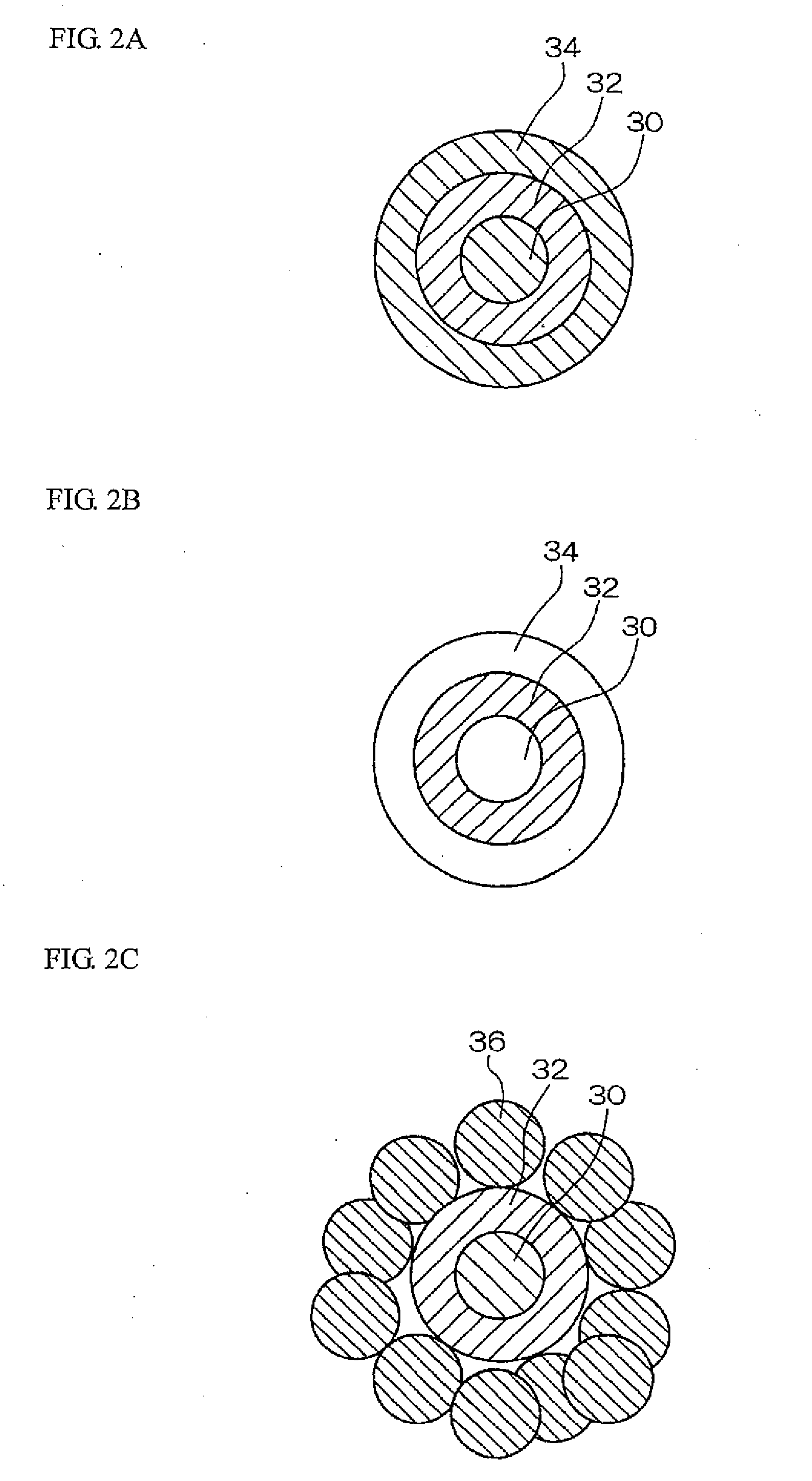
[0044] First, core-shell particles are prepared. The core-shell particles are the particles having a cross-sectional structure as shown in FIG. 2(1), in which the core particle is made of poly(methyl methacrylate) (PMMA) and coated with a copolymer of polyacrylonitrile and polymethacrylic acid (95:5 in molar ratio), which is further coated with PMMA. The diameter of the core-shell particle is 350 μm.

[Preparation of Core-Shell Particles by Two-Stage Soap-Free Polymerization]

[0045] 35 ml of methyl methacrylate (MMA), 35 mg of potassium persulfate (KPS) and 350 ml of deionized water are mixed and bubbling of a Nitrogen gas is performed for 0.5 hours while stirring. The temperature is then raised up to 70° C., and polymerization is performed while stirring for 4.5 hours. The reaction is further performed at a temperature of 80° C. for 0.5 hours.

[0046] 90 ml of thus obtained emulsion that contains PMMA particles, 4 ml of acrylonitrile (AN), 5 mg of KPS, and 270 ml of deionized water a...


PUM

PropertyMeasurementUnit
temperatureaaaaaaaaaa
diameteraaaaaaaaaa

Abstract

A carbon nanomaterial produced by: performing centrifugal melt spinning of core-shell particles that are prepared by using fine particles containing a carbon precursor polymer and a thermally decomposable polymer that disappears as a result of heat treatment, wherein the core-shell particles are heated up to a temperature at which phase separation thereof is not caused, and pressed against a plate-like heater 12 having a large number of pores 12A that penetrate therethrough in a thickness direction of the plate-like heater using centrifugal force; making the fiber obtained by the centrifugal melt spinning infusible; and performing carbonization thereof. According to this method, a carbon nanomaterial such as a carbon nanotube or a carbon nanofiber can be produced with high efficiency.

Description

TECHNICAL FIELD [0001] The invention relates to a method of producing a carbon nanomaterial and to a centrifugal melt spinning apparatus, and more specifically, relates to a method of producing a carbon nanomaterial that is suitable for production of carbon nanomaterials such as carbon nanotubes and carbon nanofibers, and a centrifugal melt spinning apparatus that is directly used in the carbon nanomaterial production method. BACKGROUND ART [0002] Conventionally, as a method of producing carbon nanotubes, a polymer blend spinning technique is known (for example, see Patent Document 1 below). Specifically, in this method, a thermally decomposable polymer that disappears as a result of heat treatment and a carbon precursor polymer that leaves carbon after heat treatment are used as starting materials to prepare a polymer blend, and the polymer blend is stretched by melt-spinning, then the carbon precursor polymer is made infusible, and thereafter carbonized to produce carbon nanotubes...

Claims


Application Information

Patent Timeline
Patent Type & Authority Applications(United States)
IPC IPC(8): C01B31/00
CPCB82Y30/00C01B31/02D01F9/20D01D5/18C01B31/36Y10S977/842C01B32/05C01B32/956C01B32/977
Inventor OYA, ASAOSANDO, TERUKAZU
Owner GUNMA UNIVERSITY
Why Eureka
Try Eureka