Process for Producing Rigid Polyurethane Foam

a polyurethane foam and manufacturing method technology, applied in the field of manufacturing methods of rigid polyurethane foam, can solve the problems of difficult use outside of mass production lines, difficult to penetrate into rigid polyurethane foam, and stop the production of hydrochlorofluorocarbons such as hcfc-141b at the end of 2003, and achieve excellent adhesiveness, little deterioration, and good stability.

Inactive Publication Date: 2008-03-13
TOHO CHEM IND
View PDF7 Cites 9 Cited by
  • Summary
  • Abstract
  • Description
  • Claims
  • Application Information

AI Technical Summary

Benefits of technology

[0028] According to the present invention, it is possible to provide a rigid polyurethane foam that is suited to water or carbon dioxide blowing, and whose thermal conductivity rate exhibits little deterioration over time; the rigid polyurethane foam also having excellent adhesiveness with little friability and excellent dimensional stability.
[0029] The present invention will be described in detail below, including a brief background leading up to achievement of the present invention.
[0030] In general, the thermal conductivity rate of rigid polyurethane foam includes the thermal conductivity of gas in cells, the thermal conductivity from radiation, the thermal conductivity of a solid layer based on heat passing through the resin, and the thermal conductivity from convection. Carbon dioxide-blown rigid polyurethane foam has a high thermal conductivity rate and poor heat insulation performance. This is said to be due to the high thermal conductivity rate of carbon dioxide compared to the thermal conductivity rate of chlorofluorocarbon gas. By setting the blowing agent to 100% water and fixing the molar quantity of carbon dioxide in the formulation, the thermal conductivity of gas can be made constant. If the diameter of cells in the rigid polyurethane foam can be fixed, then the thermal conductivity from radiation can be largely made constant. Convection does not occur with cells having a diameter of 0.4 mm or less, and therefore the thermal conductivity from convection can be ignored.
[0031] Thus, in fixing the above-mentioned conditions and the cell diameter and changing only the polyol, it should be possible to learn the correlation between the thermal conductivity of the solid layer and the polyol by preparing an all water-blown rigid polyurethane foam and measuring the initial value of the thermal conductivity rate. However, measurement results obtained in the above manner showed that there was almost no difference between common polyols regarding the initial value of the thermal conductivity rate for all water-blown rigid polyurethane foam. Next, the molar quantity of carbon dioxide in the formulation was likewise made constant, while fixing the polyol and varying the cell diameter. The thermal conductivity rate was then measured. In theory, a smaller cell diameter should lead to less thermal conductivity from radiation. However, in the case of 100% rigid polyurethane foam, the formulation with the smallest cell diameter size showed only a slight decrease in the initial value of the thermal conductivity rate, and there was no large difference compared to the thermal conductivity rates of formulations with common cell diameter sizes. Accordingly, the effect of the thermal conductivity of gas is considered to be much greater than that due to the thermal conductivity from radiation or the thermal conductivity of the solid layer based on heat passing through the resin. Achieving a considerable improvement in the initial value of the thermal conductivity rate by changing only the polyol is also considered difficult.
[0032] The inventors of the present invention focused on increasing the carbon dioxide barrier property of a resin structuring the rigid polyurethane foam in order to seal carbon dioxide in cells, thereby minimizing over-time variations in the thermal conductivity rate. Provided that the initial value for the thermal conductivity rate of the carbon dioxide-blown rigid polyurethane foam is within an allowed limit and the over-time change of the thermal conductivity rate is similar to that for HCFC-141b, then it should be possible to use such rigid polyurethane foam in applications for the refrigeration field without resulting in considerable design changes. Moreover, if such a feat can be achieved, then an improvement in dimensional stability can also be expected.
[0033] In order to promote the permeation of carbon dioxide in cells of all water-blown rigid polyurethane foam, panel foam was cut to a thickness of 16 mm, left at normal temperature and then measured. FIG. 1 shows a graph of the over-time change in thermal conductivity rates for a core foam cut to a 16-mm thickness, overall foam, and steel face-plated foam, which were similarly formulated (using a raw material named Hycel M-595 manufactured by Toho Chemical Industry Co., Ltd.) by all water blowing. Note that for comparison purposes, the result for a common chlorofluorocarbon-blown rigid polyurethane foam (using a raw material named Hycle M-505 manufactured by Toho Chemical Industry Co., Ltd.) is also shown in FIG. 1. Upon comparison, it can be seen that the thermal conductivity rate of the core foam continues to deteriorate from the initial value. After 60 to 90 days, the thermal conductivity rate becomes a constant value and attains equilibrium. The constant value was approximately 0.032 to 0.033 W / mK (0.028 kcal / mh° C.). This is considered to be the result of carbon dioxide in cells permeating and escaping over time from the resin film structuring the cells, and subsequently being replaced with air. On the other hand, the overall foam required approximately 150 days to reach 0.033 W / mK. Meanwhile, the thermal conductivity rate of the steel face-plated foam, similar to that of the HCFC-141b-blown formulation, continued to deteriorate over time for more than 150 days. The slow speed of deterioration meant the evaluation took time. Accordingly, the over-time deterioration of the thermal conductivity rate was evaluated using the value after 60 days of a core foam cut to 16 mm. The evaluation was performed with a comparison of the initial value and measurement values after the 14th and 28th days as a measure of the deterioration speed. As a target, the inventors aimed to make the thermal conductivity rate after 60 days of the core foam cut to 16 mm comparable to the 0.026 W / mK after 60 days of the HCFC-141b-blown formulation, and considerably lower than the 0.033 W / mK of the all water-blown formulation.

Problems solved by technology

In cases where a large amount of 1,1-dichloro-1-fluoroethane (HCFC-141b) is used as a conventional blowing agent, the thermal conductivity of the obtained rigid polyurethane foam is good and chlorofluorocarbon gas does not easily penetrate into the rigid polyurethane foam from outside.
However, the manufacturing of hydrochlorofluorocarbons such as HCFC-141b was stopped at the end of 2003 due to the destructive effect on the ozone layer.
However, all of these possess various disadvantages compared to hydrochlorofluorocarbon.
For example, the hydrocarbon blowing agent is considered a hazardous material under fire protection laws, and requires a large sum of capital investment that makes usage difficult outside of mass production lines such as that for refrigerators.
Hydrofluorocarbons have a greenhouse effect that impacts global warming, and there is a risk that future use will not be possible.
However, the high gas thermal conductivity rate of carbon dioxide compared to chlorofluorocarbon leads to a problem where there is considerable deterioration of the heat insulation performance of such rigid polyurethane foam compared to related art in general.
Usage may not be possible in cases where the insulation thickness cannot be increased due to the product shape, installation location or the like, and rigid polyurethane foam is particular unsuitable for use as a heat insulation material in the field of refrigeration.
Therefore of course in cases of all water blowing (100% water blowing), but also in cases where the original proportion of water used in the formulation is high, there still remains the problem of being unable to maintain the initial value of the thermal conductivity rate of the rigid polyurethane foam over a long period.
This problem also exists in cases where carbon dioxide in a supercritical, subcritical, or liquid state, or the like is used as a blowing agent, and is very difficult to resolve.
If a large amount of carbon dioxide is used for the blowing agent, then the thermal conductivity rate of a rigid polyurethane foam obtained from a polyether polyol thereof exhibits particularly significant deterioration over time.
Accordingly, for fields where heat insulation performance is particularly required, use of substances such as the following at present is unavoidable: HFC-245fc or HFC-365mfc, which are expensive greenhouse gases that are difficult to handle due to a low boiling point or combustibility; and cyclopentane, which is combustible and requires a large amount of investment for manufacturing equipment.
Therefore, rigid polyurethane foam that uses a large amount of water in formulation is more likely to become a weak foam with a low molecular weight, because polymerization does not adequately proceed under a lower temperature environment during blowing.
Such a state is known as friability, and rigid polyurethane foam with friability does not exercise adequate self-adhesiveness to a joining surface.
Therefore, defects such as detachment, separation, and the like are likely to occur under a low temperature environment.
On the other hand, in the case of rigid polyurethane foam that uses a large amount of water in the formulation, it is generally necessary to increase the temperature of the surface to 45 to 50° C., making blowing under blowing conditions similar to the ambient air temperature or the like extremely difficult.
However, in the case of all water-blown rigid polyurethane foam, adhesion failure due to friability becomes a problem.
In other words, there exists a problem where rigid polyurethane foam that uses a large amount of water in the formulation is prone to adhesion failure under a low temperature environment.
Furthermore, rigid polyurethane foam blown by carbon dioxide is known to have worse dimensional stability and a larger dimensional change rate at low density levels compared to foam blown by the conventional HCFC-141b.
Such foam when left under normal temperatures gradually shrinks over a long period, and abnormalities in the appearance of the product may ultimately result.
A cause behind this is considered to be carbon dioxide in cells in the foam that becomes more likely to pass through the polyurethane resin film to outside, and thus become more prone to being released outside.
However, using such polyols would make it difficult to obtain a rigid polyurethane foam that adequately achieves the required performance needed for practical application, such as a low thermal conductivity rate with little deterioration over time, low friability and excellent adhesiveness under low temperature environments, and excellent dimensional stability.

Method used


Image

  • Process for Producing Rigid Polyurethane Foam
  • Process for Producing Rigid Polyurethane Foam
  • Process for Producing Rigid Polyurethane Foam

Examples


example 1

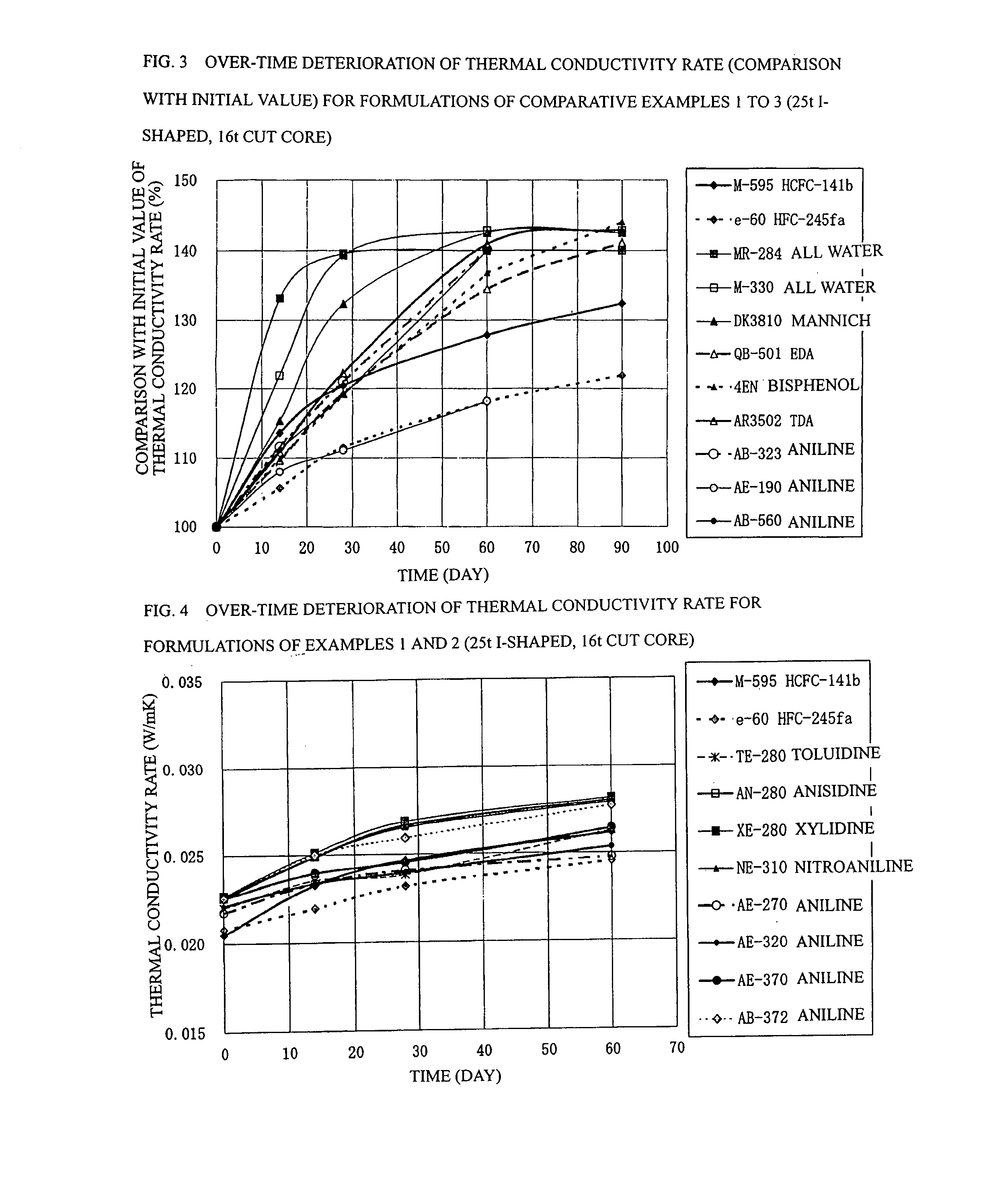
[0084] In example 1 shown in Table 4, panels were prepared using the following formulations: a formulation (12) having a ratio of 5.50 parts by mass of water, 0.61 part by mass of TMHDA, 1.5 part by mass of SZ-1718 manufactured by Dow Corning Toray Co., Ltd. (formerly Nippon Unicar Co., Ltd.), and 197.0 parts by mass of Millionate MR-200 manufactured by Nippon Polyurethane Industry Co., Ltd. based on 100 parts by mass of a Toho polyol TE-280 manufactured by Toho Chemical Industry Co., Ltd. so as to achieve a total mass of 300 g; a formulation (13) having a ratio of 5.36 parts by mass of water, 1.04 part by mass of TMHDA, 1.5 part by mass of SZ-1718, and 189.7 parts by mass of MR-200 based on 100 parts by mass of a Toho polyol AN-280 manufactured by Toho Chemical Industry Co., Ltd. so as to achieve a total mass of 300 g; a formulation (14) having a ratio of 4.36 parts by mass of water, 1.04 part by mass of TMHDA, 1.5 part by mass of SZ-1718, and 189.7 parts by mass of MR-200 based on...

example 2

[0086] In example 2 shown in Table 5, panels were prepared using the following formulations: a formulation (16) having a ratio of 5.60 parts by mass of water, 1.09 part by mass of TMHDA, 1.5 part by mass of SZ-1718 manufactured by Dow Coming Toray Co., Ltd. (formerly Nippon Unicar Co., Ltd.), and 203.1 parts by mass of Millionate MR-200 manufactured by Nippon Polyurethane Industry Co., Ltd. based on 100 parts by mass of a Toho polyol AE-270 manufactured by Toho Chemical Industry Co., Ltd. so as to achieve a total mass of 300 g; a formulation (17) having a ratio of 5.15 parts by mass of water, 1.00 part by mass of TMHDA, 1.5 part by mass of SZ-1718, and 178.2 parts by mass of MR-200 based on 100 parts by mass of a Toho polyol AE-320 manufactured by Toho Chemical Industry Co., Ltd. so as to achieve a total mass of 300 g; a formulation (18) having a ratio of 4.78 parts by mass of water, 0.53 part by mass of TMHDA, 1.5 part by mass of SZ-1718, and 158.9 parts by mass of MR-200 based on ...

example 3

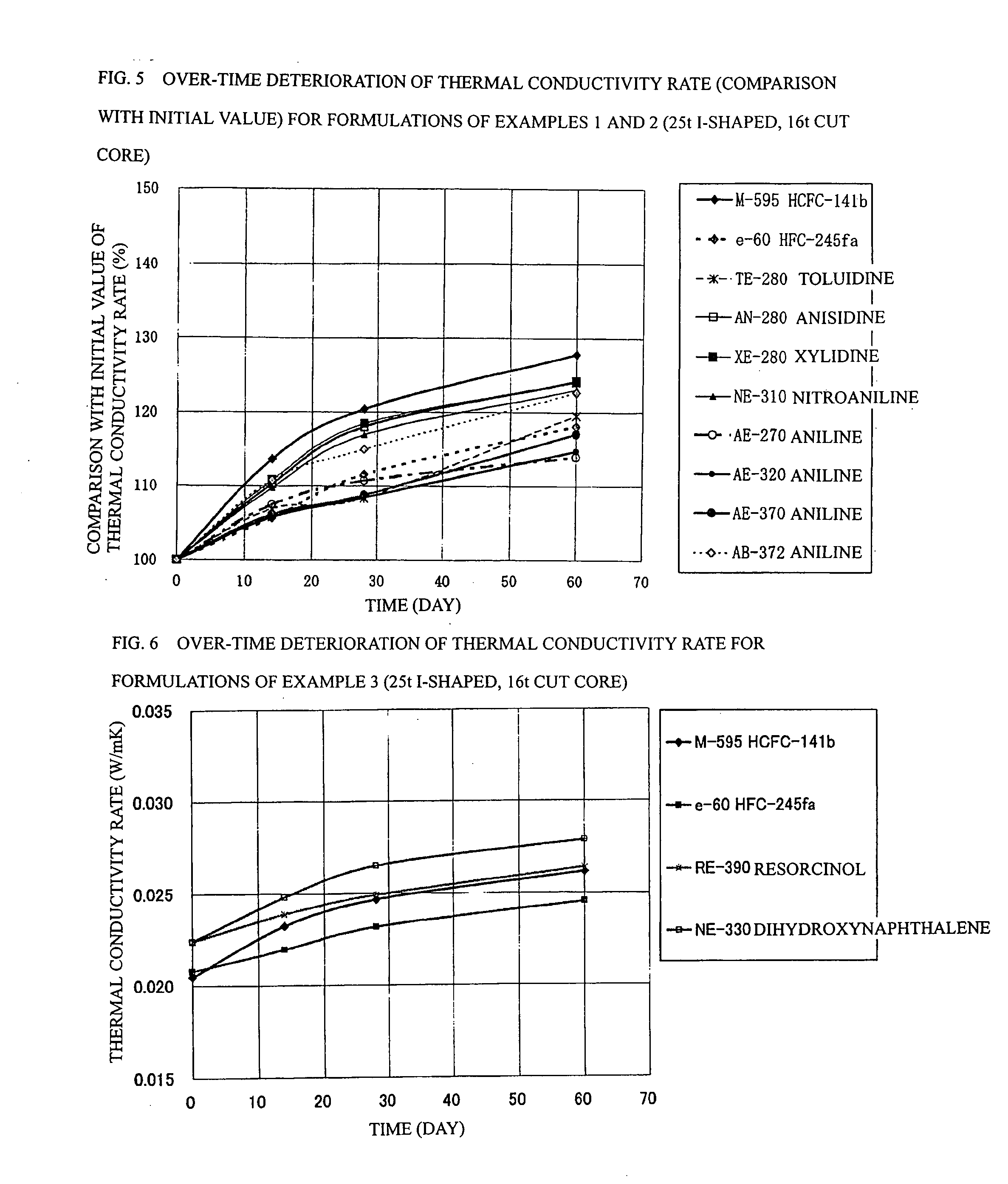
[0092] In example 3 shown in Table 6, panels were prepared using the following formulations: a formulation (20) having a ratio of 5.43 parts by mass of water, 1.06 part by mass of TMHDA, 1.5 part by mass of SZ-1718 manufactured by Dow Coming Toray Co., Ltd. (formerly Nippon Unicar Co., Ltd.), and 193.5 parts by mass of Millionate MR-200 manufactured by Nippon Polyurethane Industry Co., Ltd. based on 100 parts by mass of a Toho polyol RE-390 manufactured by Toho Chemical Industry Co., Ltd. so as to achieve a total mass of 300 g; and a formulation (21) having a ratio of 5.01 parts by mass of water, 0.97 part by mass of TMHDA, 1.5 part by mass of SZ-1718, and 170.6 parts by mass of MR-200 based on 100 parts by mass of a Toho polyol NE-330 manufactured by Toho Chemical Industry Co., Ltd. so as to achieve a total mass of 300 g.

[0093] The formulation (20) in example 3 is a polyol in which ethylene oxide and propylene oxide are subjected to addition to resorcin at a mass ratio of 100 / 0, a...


PUM

PropertyMeasurementUnit
mass ratioaaaaaaaaaa
temperatureaaaaaaaaaa

Abstract

The present invention provides a manufacturing method of a rigid polyurethane foam for a heat insulation material that satisfies performance required for practical use, such as a low thermal conductivity over a long period, and excellent adhesiveness and excellent dimensional stability under a low temperature environment. The manufacturing method of a rigid polyurethane foam for a heat insulation material, which is formed from blowing and molding using a mixture that includes polyisocyanate, a polyol, and a blowing agent, wherein a polyol prepared by addition-polymerizing ethylene oxide and propylene oxide to an aromatic monoamine compound or an aromatic diol compound.

Description

TECHNICAL FIELD [0001] The present invention relates to a manufacturing method of rigid polyurethane foam that is used as a thermal insulation material. More specifically, the present invention relates to a rigid polyurethane foam that maintains a low thermal conductivity rate over a long period and has good adhesiveness under a low temperature environment. BACKGROUND ART [0002] Rigid polyurethane foam is formed from blowing and molding using a mixture that includes polyisocyanate, a polyol, a blowing agent, and auxiliary additives such as catalysts and flame retardants. Rigid polyurethane foam is widely used as a material with excellent shapeability. Unlike fitted heat insulation materials such as expanded polystyrene, rigid polyurethane foam adheres itself to a face material or the like during blowing and has the advantage of increased strength as a composite structural member. In addition, rigid polyurethane foam can be formed by various blowing methods such as injection blowing ...

Claims


Application Information

Patent Timeline
Patent Type & Authority Applications(United States)
IPC IPC(8): C08L75/04
CPCC08G18/4879C08G18/5027C08G2330/00C08G2101/0083C08G2101/0025C08G2110/0025C08G2110/0083
Inventor HASEGAWA, MIKIOKAWA, TADASHINOGUCHI, TOMOHIRO
Owner TOHO CHEM IND
Why Eureka
Try Eureka