System And Method For Removing Contaminants

a technology of removing system and removing method, applied in the direction of specific gravity measurement, using mechanical means, domestic heating, etc., can solve the problems of small amount of contaminants still liable to be present in the gas at concentrations sufficient to damage the tool optics, lint, dead skin and manufacturing debris, etc., to achieve high-efficiency filtering and prolong the time period

Active Publication Date: 2008-04-03
ENTEGRIS INC
View PDF24 Cites 115 Cited by
  • Summary
  • Abstract
  • Description
  • Claims
  • Application Information

AI Technical Summary

Benefits of technology

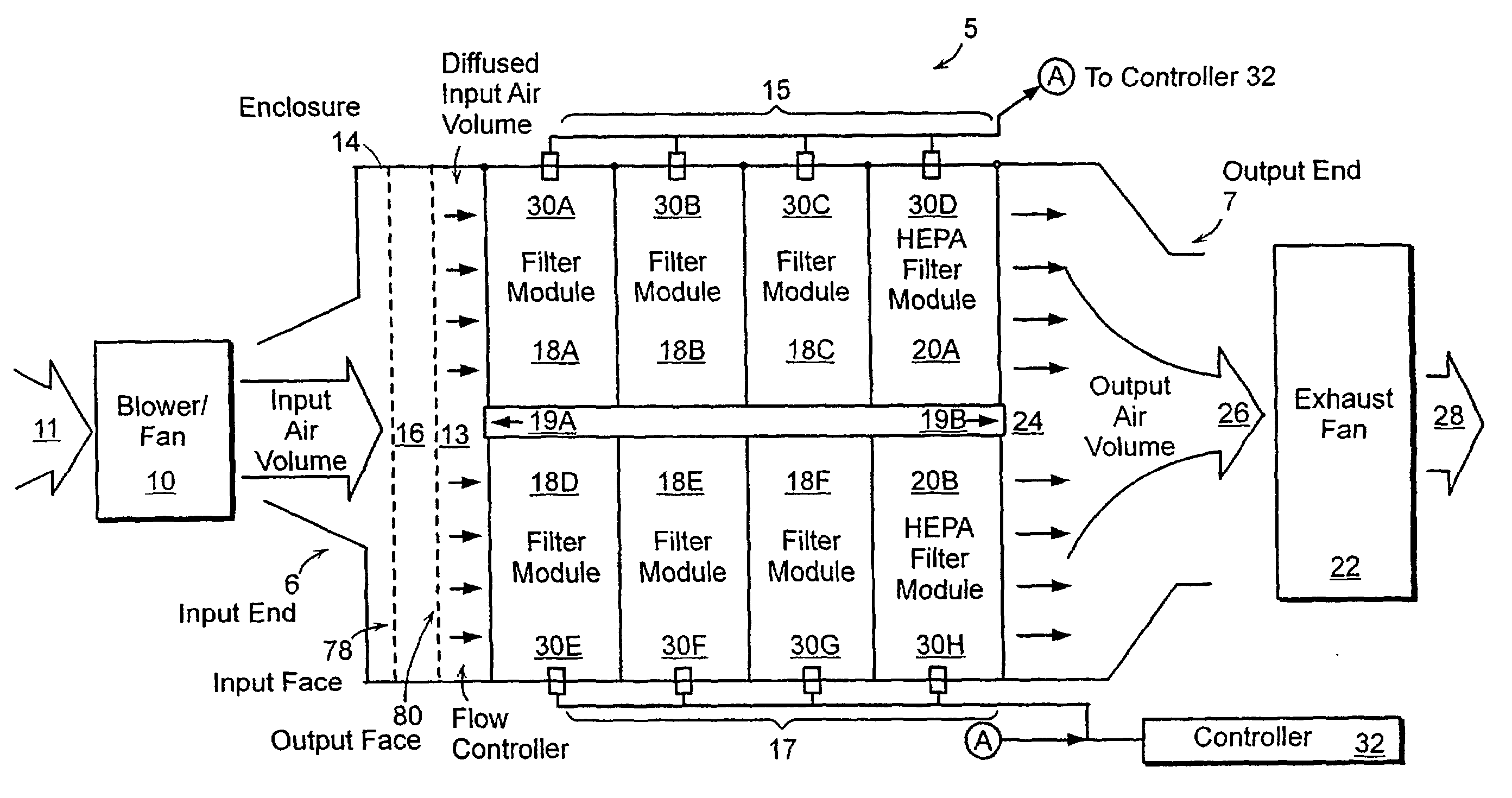
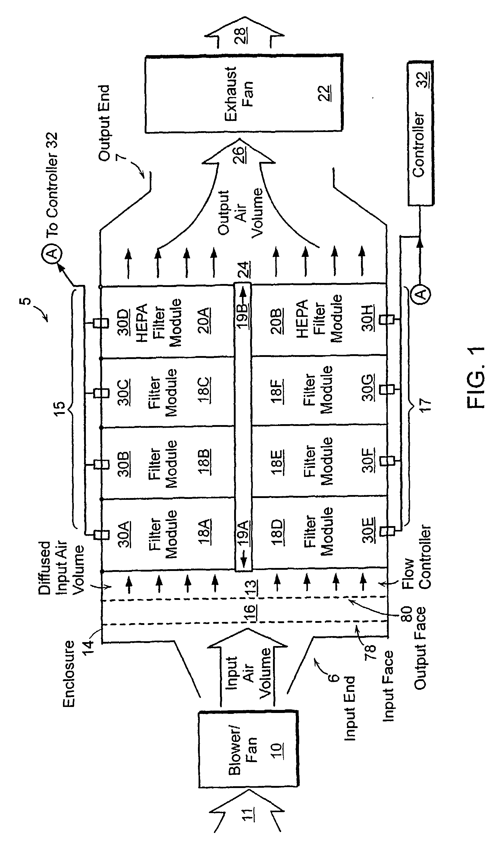
[0008]Embodiments of the invention may be used to filter an incoming air supply to remove airborne contaminants. Moreover, embodiments of the invention may be used to monitor gas flow quality for the removal of contaminants such as, for example, be yield-reducing contaminants. Parallel filter stages are employed to provide highly efficient filtering as well as to provide longer time periods between filter changes. Embodiments of the invention empl

Problems solved by technology

Common particulate contaminants include dust, lint, dead skin and manufacturing debris.
Although purified dry air, nitrogen or the like is generally used to drive pneumatics and purge optics, small amounts of contaminants are still liable to be present in the gas at concentrations sufficient to damage tool optics, for example, illuminator optics and projection lenses.
Scattered or absorbed light in photolithography optical surfaces causes distortion of the spherical quality of wavefronts.
When the information contained in the spherical wavefront is distorted, the resulting image is also misformed or abberated.
Image distortions, or in the case of photolithography, the inability to accurately reproduce the circuit pattern on the reticle, cause a loss of critical dimension control and process yie

Method used


Image

  • System And Method For Removing Contaminants
  • System And Method For Removing Contaminants
  • System And Method For Removing Contaminants

Examples


example

[0095]A study of the gas volumetric throughput through a sampling tube orifice of the invention was conducted. The study involved monitoring the volumetric flow of gas into the orifice and the corresponding flow from the orifice. The gas flow through the tube orifice can be measured by using standard equipment such as a volumetric flow meter. The volumetric throughput was measured for about 30 seconds. An average volumetric flow into the tube orifice and therethrough was obtained from a sample population of 61. The results of the study are provided in Table 1.

TABLE 1MinimumAverageMaximumSamplingVolumetric GasVolumetric GasVolumetric GasTube OrificeFlow (ft3 min−1)Flow (ft3 min−1)Flow (ft3 min−1)Input0.004290.004060.00389Output0.003940.003980.00400

Table 1 shows that a relatively low volume of gas flows through the tube orifice at a high velocity. The results in Table 1 also indicate that the volume of gas flow is consistent as minimum and maximum flow values do not substantially devi...


PUM

PropertyMeasurementUnit
Flow rateaaaaaaaaaa
Diameteraaaaaaaaaa
Diameteraaaaaaaaaa

Abstract

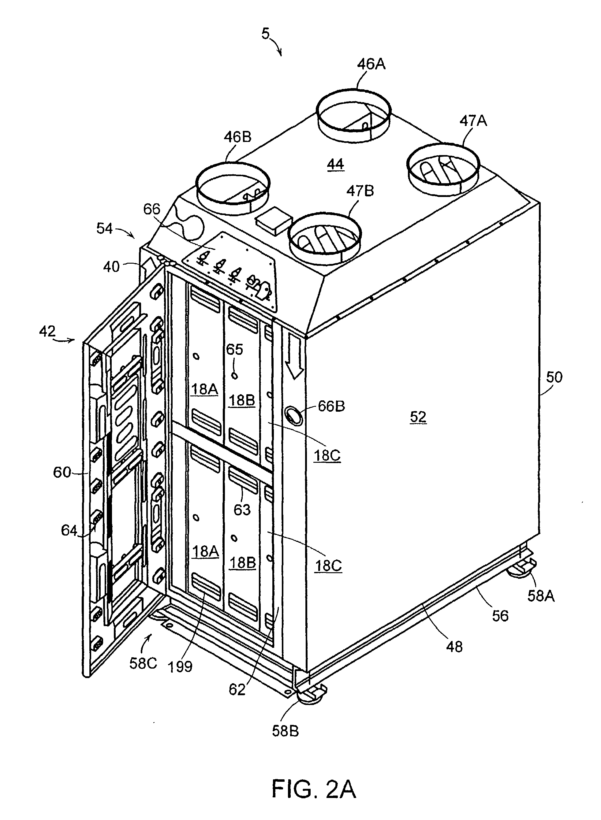
The invention provides a system and method comprising an apparatus for removing contaminants from a gas in a semiconductor processing device, which can include a filter unit having at least two parallel filter stages located therein. The filter stages are designed to remove a least a portion of the contaminants present in the gas flowing through them. The apparatus can also include a flow controller for distributing the gas flow among the filter stages. In one embodiment, the controller may consist of a diffuser plate. The invention also provides a sampling tube orifice for gas flow control in a system or method of the invention. In another embodiment, an apparatus for removing contaminants from a gas in a clean room comprises a filter unit having at least two parallel filter stages, which are used to remove a portion of the contaminants in the gas as it passes through the apparatus.

Description

CROSS REFERENCE TO RELATED APPLICATIONS[0001]This application claims the priority of U.S. Provisional Application No. 60 / 577,723 filed Jun. 7, 2004 and entitled, SYSTEM AND METHOD FOR REMOVING CONTAMINANTS, and U.S. Provisional Application No. 60 / 619,857 filed Oct. 18, 2004 and entitled, SYSTEM AND METHOD FOR REMOVING CONTAMINANTS, which are hereby incorporated by reference herein.BACKGROUND OF THE INVENTION[0002]Clean rooms are utilized in many industries for contamination control and to improve product quality and product yields. By way of example, clean rooms may be employed in pharmaceutical, biotechnology and semiconductor applications. Semiconductor manufacturing environments will be used hereinbelow and shall serve as an illustrative environment.[0003]Airborne contaminants must be reduced, eliminated or both to help ensure optimum semiconductor yields. Therefore, gas filtration is critical in semiconductor manufacturing environments. Tremendous efforts are made to eliminate y...

Claims


Application Information

Patent Timeline
IPC IPC(8): B01D53/04B01D46/12F24F3/16G01N1/22G01N30/00G01N7/00
CPCB01D46/0013B01D46/10B01D46/429B01D46/521B01D2273/30B01D53/0454B01D2258/0216B01D2259/402B01D53/0446B33Y80/00B01D53/04B01D46/12F24F8/108F24F8/158F24F8/15
Inventor SERGI, JOHN E.GAUDREAU, JOHNKISHKOVICH, OLEG P.GOODWIN, WILLIAMKINKEAD, DEVON A.
Owner ENTEGRIS INC
Why Eureka
Try Eureka