Photoelectric Converter, and Transparent Conductive Substrate for the same

a technology of photoelectric converter and conductive substrate, which is applied in the direction of electrolytic capacitor, light-sensitive device, electrochemical generator, etc., can solve the problems of low productivity, radioactive contamination of nuclear energy, various global or local environmental issues, etc., and achieve excellent photoelectric conversion efficiency, improve photoelectric conversion efficiency, and high durability

Inactive Publication Date: 2008-04-10
SONY CORP
View PDF2 Cites 37 Cited by
  • Summary
  • Abstract
  • Description
  • Claims
  • Application Information

AI Technical Summary

Benefits of technology

[0025]The present invention dramatically improves the photoelectric conversion efficiency by arranging a conductive interconnection layer in an electrode. In addition, it provides a highly durable transparent conductive substrate with excellent photoelectric conversion efficiency which is prevent

Problems solved by technology

Nuclear energy, if used, may be at risk for radioactive contamination.
Continuous full dependence on such conventional energy will cause various global or local environmental issues.
These crystalline silicon solar cells, however, require much energy and time for growing their crystals, thereby have low productivity and are disadvantageous in cost, although they show a higher conversion efficiency than that of amorphous silicon.
Amorphous silicon solar cells, however, require vacuum processes, and this is still a large burden on facilities.
However, solar cells of this type have a very low photoelectric conversion efficiency of 1% or less and show poor durability.
However, current commercially available transparent conductive substrates, if used for the production of large-area photoelectric converters, have a high surface electr

Method used


Image

  • Photoelectric Converter, and Transparent Conductive Substrate for the same
  • Photoelectric Converter, and Transparent Conductive Substrate for the same
  • Photoelectric Converter, and Transparent Conductive Substrate for the same

Examples


example 1

[0133]Initially, a TiO2 paste for constituting a semiconductor particle layer 4 was prepared.

[0134]The TiO2 paste was prepared according to a procedure with reference to “Latest Technologies for Dye-sensitizing Solar Cells” (CMC Publishing Co., Ltd.).

[0135]Titanium isopropoxide (125 ml) was gradually added dropwise to 750 ml of a 0.1 M aqueous nitric acid solution at room temperature with stirring. After the completion of dropwise addition, the mixture was transferred to a thermostat at 80° C. and was stirred for 8 hours to thereby yield a whitish semitransparent sol. This sol was gradually cooled to room temperature, filtrated through a glass filter, and measured up to 700 ml.

[0136]The above-prepared sol was transferred to an autoclave and subjected to hydrothermal treatment at 220° C. for 12 hours. Thereafter, dispersion was conducted by ultrasonic treatment for one hour. The dispersed sol was concentrated at 40° C. on an evaporator to have a TiO2 content of 20 percent by weight.

[...

examples 2 to 4

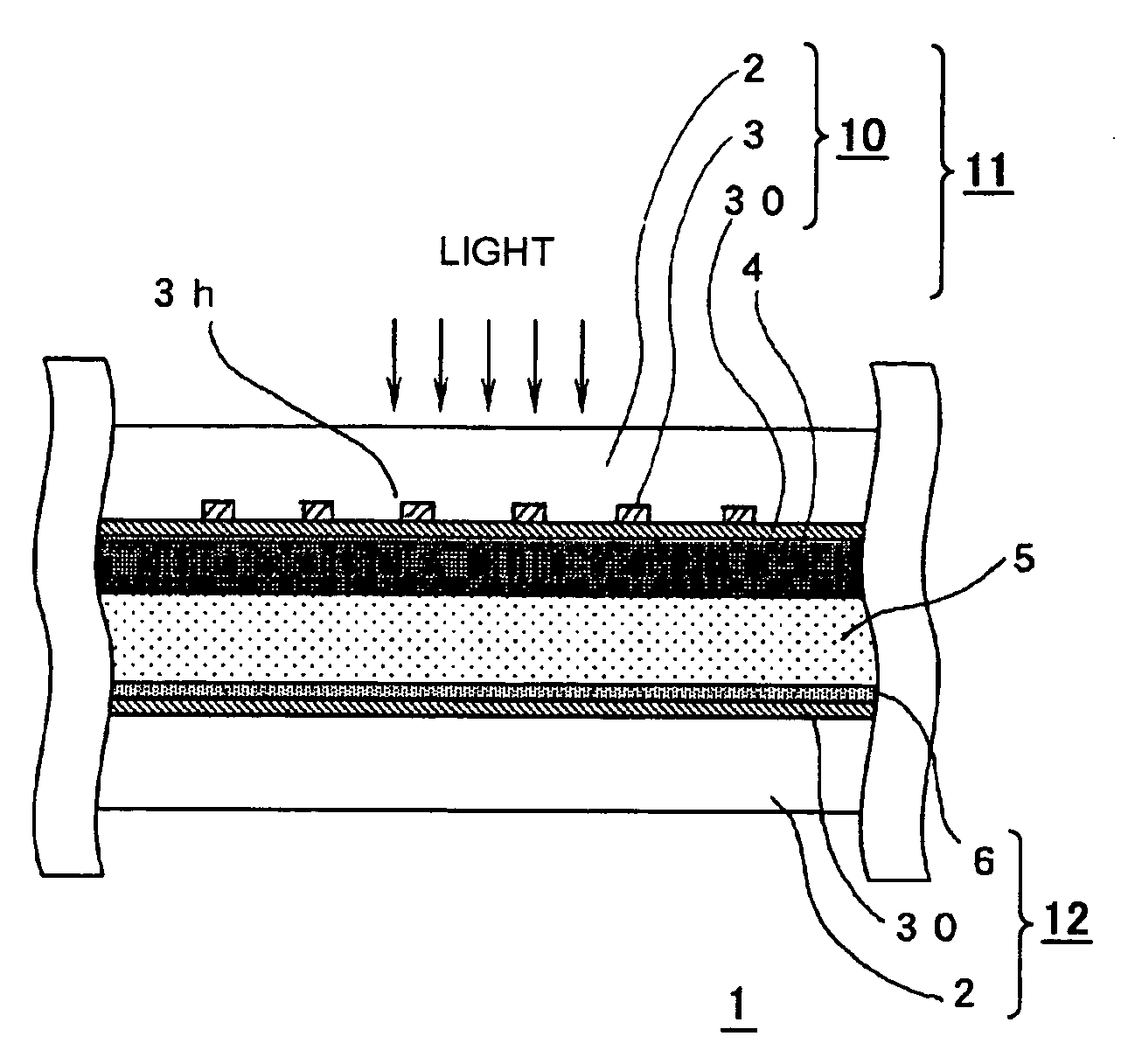
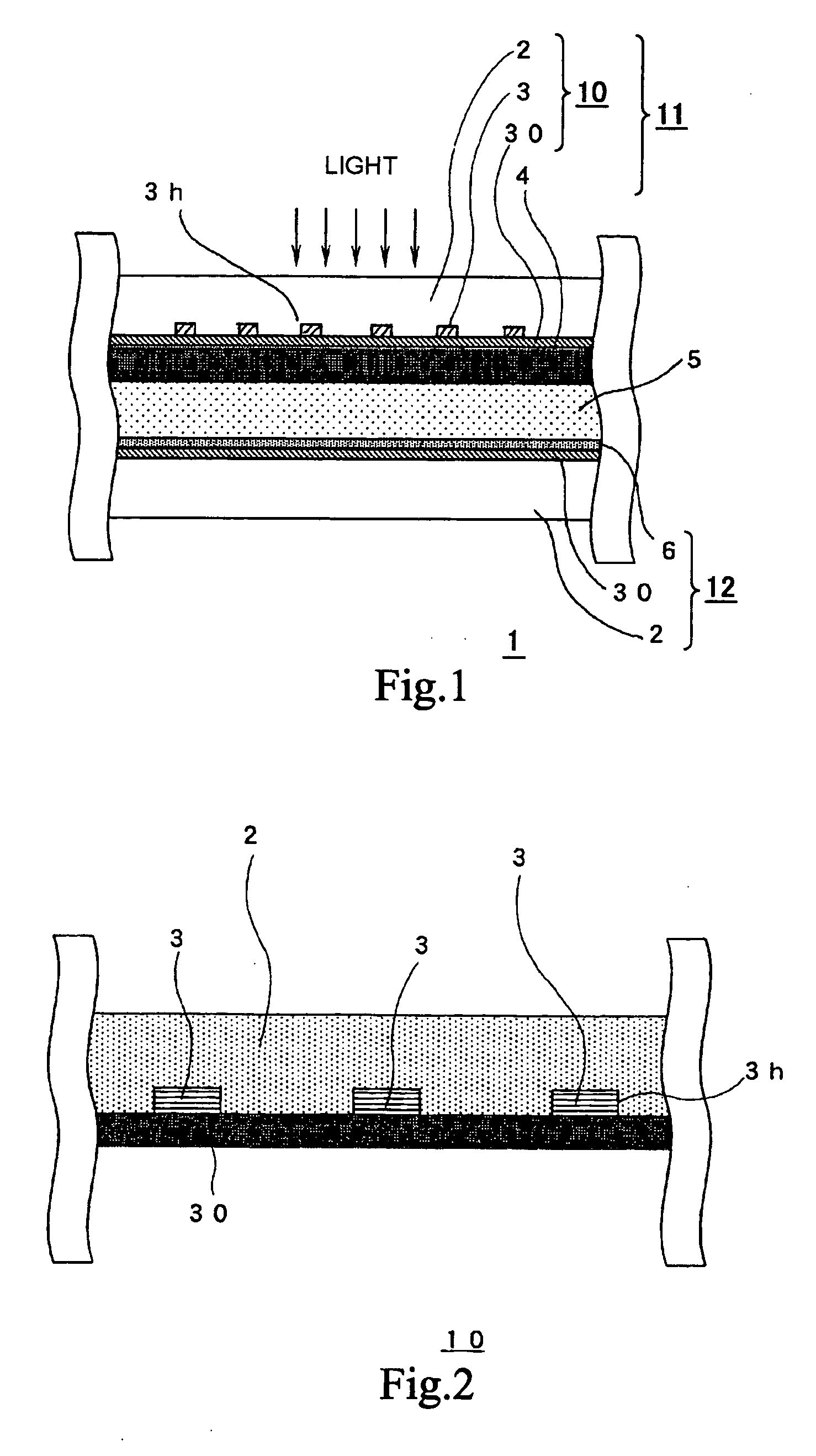
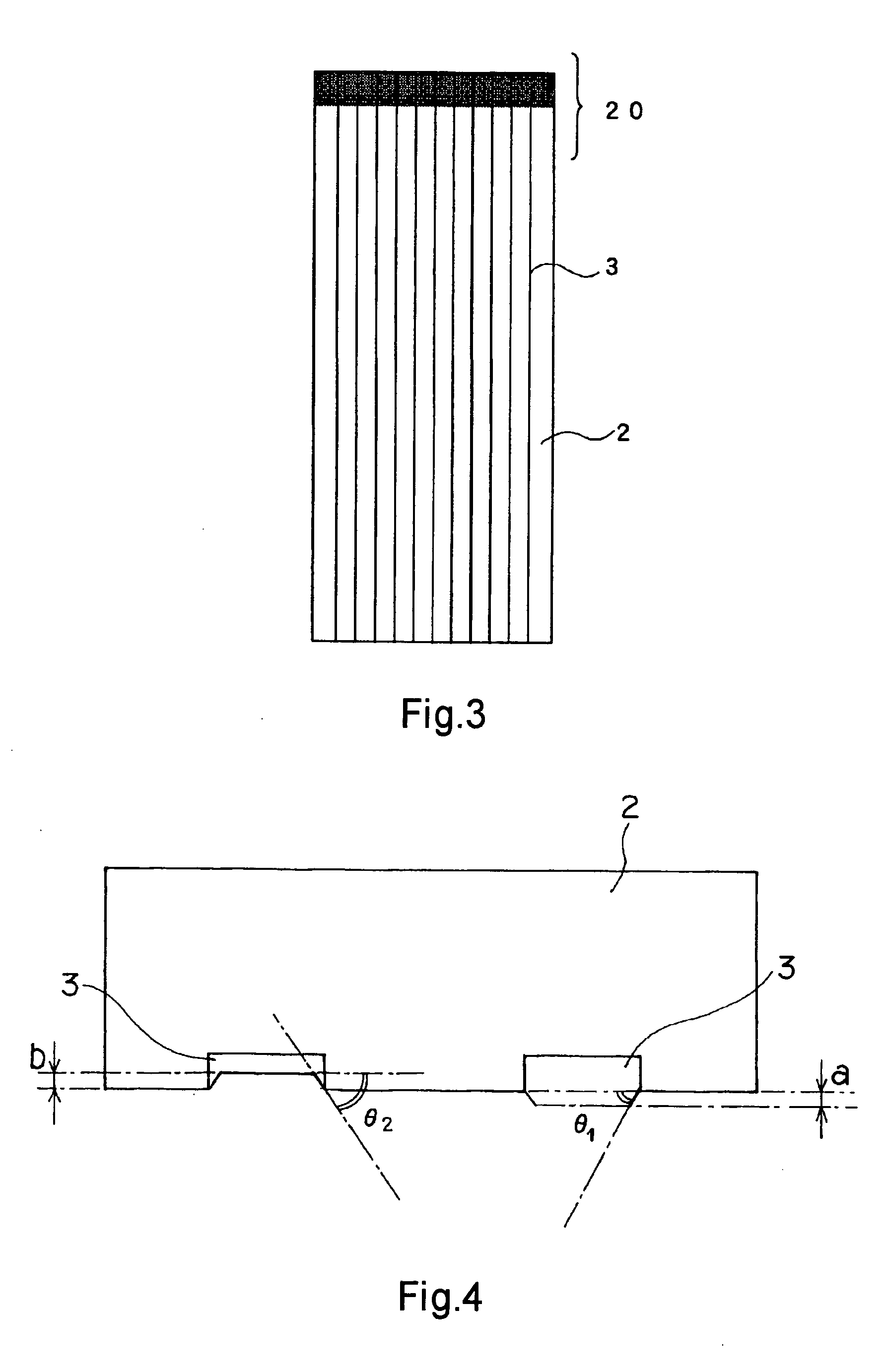
[0155]A series of photoelectric converters 1 was prepared under the conditions of Example 1, except for using materials for the conductive interconnection layer 3 shown in Table 1 below.

examples 5 to 7

[0156]A series of photoelectric converters 1 was prepared under the conditions of Example 1, except for forming the conductive interconnection layer 3 by printing using commercially available pastes of the materials shown in Table 1 below.


PUM


Abstract

A highly durable photoelectric converter with excellent photoelectric conversion efficiency is prevented from resistance loss or lowering of photoelectric conversion efficiency and free from problems of corrosion and reverse electron transfer reaction. Specifically disclosed is a photoelectric converter (1) comprising a semiconductor electrode (11), a counter electrode (12), and an electrolyte layer (5) arranged between the electrodes. The semiconductor electrode (11) includes a transparent conductive substrate (10) including a transparent base (2), a conductive interconnection layer (3), and a metal oxide layer (30), and a semiconductor particle layer (4) arranged on the transparent conductive substrate (10). The transparent base (2) of the transparent conductive substrate (10) has a trench (3h) on one surface, and the conductive interconnection layer (3) is embedded in this trench (3h).

Description

TECHNICAL FIELD[0001]The present invention relates to photoelectric converters, and transparent conductive substrates for the same.BACKGROUND ART[0002]Fossil fuels such as coal and petroleum, if used as energy sources, form carbon dioxide which is believed to cause global warming.[0003]Nuclear energy, if used, may be at risk for radioactive contamination.[0004]Continuous full dependence on such conventional energy will cause various global or local environmental issues.[0005]In contrast, solar cells affect the global environment very slightly and are expected to become widespread further more. This is because solar cells are photoelectric converters that use sunlight as an energy source and convert sunlight into electrical energy.[0006]For example, various solar cells using silicon as a material are commercially available, and these are broadly divided into crystalline silicon solar cells using single-crystal silicon or polycrystalline silicon, and amorphous silicon solar cells.[000...

Claims


Application Information

Patent Timeline
IPC IPC(8): H01L31/04H01G9/20H01M14/00
CPCH01G9/2022H01G9/2027Y02E10/542H01M14/005H01G9/2031
Inventor MOROOKA, MASAHIROSUZUKI, YUSUKE
Owner SONY CORP
Why Eureka
Try Eureka