Bearing systems for high-speed rotating machinery

a technology of bearing system and rotating machinery, which is applied in the direction of machines/engines, positive displacement liquid engines, pumping, etc., can solve the problems of large diameter shaft friction loss, substantial total friction loss of the complete bearing system, and inability to reduce the friction loss of the large diameter shaft, so as to eliminate the possibility of the ball skidding in the race. , the effect of reducing the possibility of the ball skidding

Inactive Publication Date: 2008-04-17
DELGADO LAUREN N
View PDF27 Cites 82 Cited by
  • Summary
  • Abstract
  • Description
  • Claims
  • Application Information

AI Technical Summary

Benefits of technology

[0023]Another object of the invention is to provide improved bearing systems for rotating shafts that accommodate axial thermal expansion and contraction of the shaft during operational rotation and that, at the same time, maintain optimum performance of the shaft supporting bearings.
[0024]A further object of the invention is to provide improved bearing systems for rotating shafts wherein the shaft is rotatably supported adjacent one end by a first ball bearing assembly capable of carrying axial thrust in both directions and is rotatably supported adjacent its opposite end by a second ball bearing assembly that is slidably mounted for axial movement in a bearing carrier and that is biased in a direction to maintain the integrity of the bearings races and balls while accommodating axial movement of the shaft.
[0025]A still further object of the invention is to provide improved bearing systems for the rotating components of a turbocharger wherein the above-described first ball bearing assembly rotatably supports the compressor wheel or cool end of the turbocharger shaft and the above-described second ball bearing assembly rotatably and slidably supports the turbine wheel or hot end of the shaft, thereby to accommodate axial expansion and contraction of the shaft while maintaining the integrity of both bearing assemblies.
[0027]Also in accordance with the invention, the second ball bearing assembly may comprise an angular contact ball bearing. The outer race of the angular contact bearing assembly is slidably mounted for axial movement in a bearing carrier or cylinder and is biased, for example by a preload spring, in a direction to maintain the outer race in contact with the balls and the balls in contact with the inner race, thereby to mitigate skidding of the balls in the races at all times during operation.
[0028]In a preferred embodiment for rotatably supporting the rotating components of a turbocharger, the improved bearing system of this invention comprises a deep groove ball bearing in the compressor end of a rotatable elongated bearing carrier or cylinder capable of carrying thrust in both directions, and an angular contact ball bearing in the turbine (hot) end of the rotatable elongated cylinder that carries a preload spring engaging its outer race. The outer race of the angular contact ball bearing is free to move axially in the rotatable elongated cylinder so that, when axial expansion of the shaft takes place, the spring force against the outer race maintains the geometric integrity of the bearing at all times, essentially eliminating any possibility of the balls skidding in the races.
[0031]The combination of the improved ball bearing systems disclosed in this invention with an intake mounted motor-generator provides the engine industry with an ideal turbo machine capable of assisting the engine during acceleration, generating electricity at high engine speeds, and embodying the highest mechanical efficiency due to the use of the double ball bearing systems.

Problems solved by technology

When the potential of turbocharging high-speed diesel and gasoline engines became obvious, the pressure output of the turbocharger compressors needed to be increased substantially and the friction losses of the large diameter shafts became unacceptable.
Since the friction loss in radial thrust bearings is a function of the fourth power of the radius, the collar attached to the shaft causes a relatively high thrust bearing friction loss which, when added to the friction loss of the sleeve bearings, results in a substantial total frictional loss for the complete bearing systems.
This residual unbalance forces the non-rotating cylinder to orbit radially at a very high frequency and causes the mating surfaces of the square retaining flange to be subject to fretting.
Thus, a solid lubricant pad was used between the mating surfaces of the square flange and corresponding stationary housing surface to mitigate the fretting problem, however, this problem still contributed to a limited service life in turbochargers using this bearing system.
This bearing system has proven to be satisfactory for use in commercial high-speed turbochargers, however, it still requires a supply of pressurized lubricant from an engine lubricating system and, historically, the use of lubricating oil in turbochargers has resulted in a number of operational problems.
There is inherently a small leak path around the piston ring seals and, during some operating conditions of the engine, such as low idle, a minor amount of oil leakage can occur.
Even small amounts of oil leakage into the compressor casing and / or turbine casing can contribute to undesirable emissions in the engine exhaust.
Another problem occurs in cold weather when the increase in viscosity of the lubricating oil causes a lag in time for the oil to reach the turbocharger bearings and, in extreme cold conditions, can cause failure of the bearings.
In addition, when an engine is shut down after being operated at high load when exhaust temperatures are maximized, residual heat can drain into the interior of the turbochargers, causing residual lube oil to carbonize.
Continuing carbon buildup can eventually lead to bearing system failure.
Finally, there is significant cost associated with providing lube oil passages in the turbocharger bearing housing and in the tubing used to carry lube oil to and away from the turbocharger.
Under normal operating conditions, the system functions satisfactorily, however, under extreme conditions where engine exhaust temperatures reach very high levels, the turbine end of the shaft experiences axial expansion that can cause the inner race of the turbine end bearing to move axially away from the outer race that is pressed into the elongated cylinder and allows the balls in the angular contact ball bearing to skid in the races.
This movement of the inner race of the turbine end bearing can cause the balls in the bearing to skid in the races.

Method used


Image

  • Bearing systems for high-speed rotating machinery
  • Bearing systems for high-speed rotating machinery
  • Bearing systems for high-speed rotating machinery

Examples


Embodiment Construction

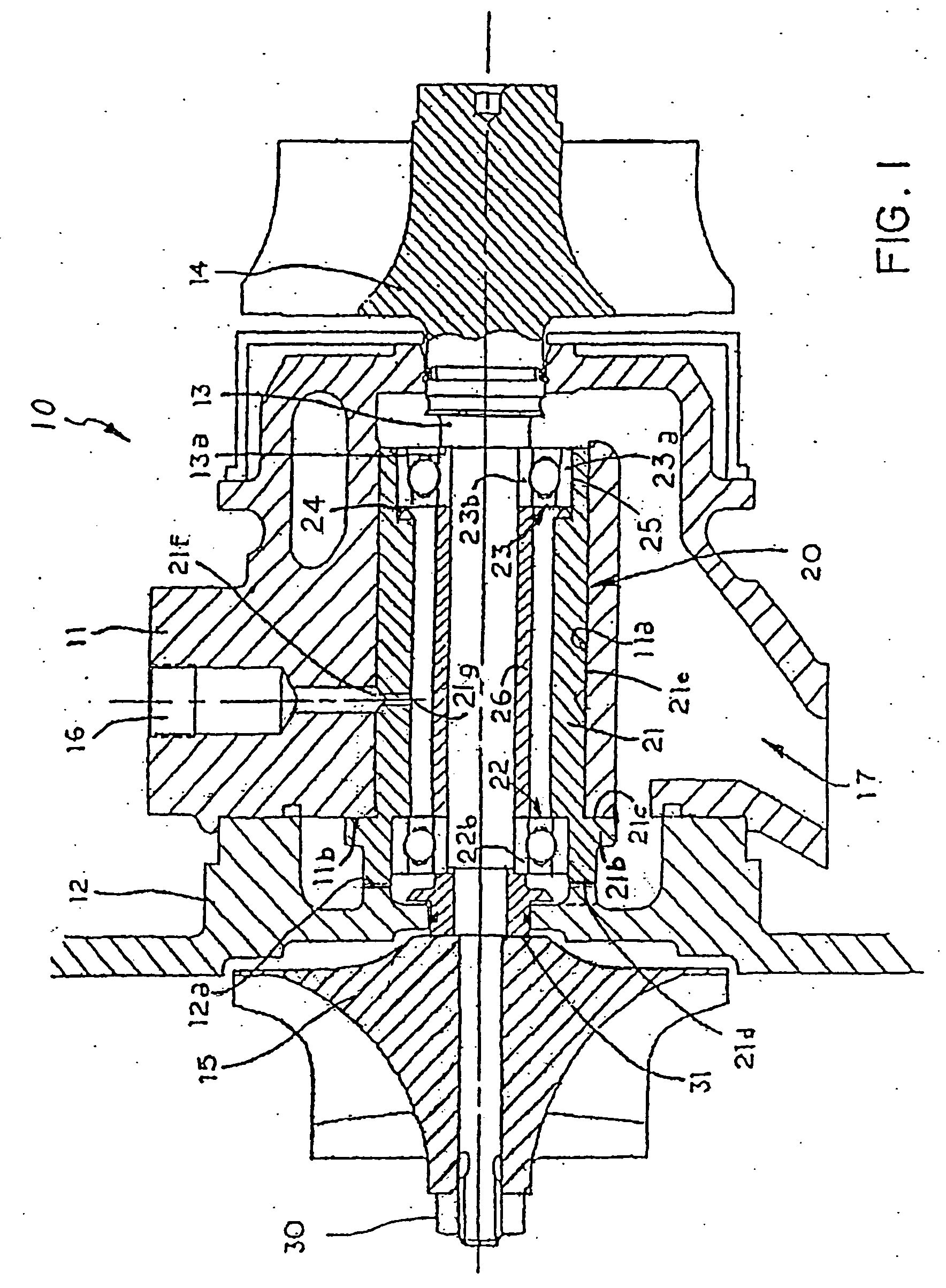
[0038]The bearing system of this invention is adapted to support, within stationary elements of a machine, a high-speed rotating shaft. FIG. 1, for example, illustrates the stationary elements of a turbocharger 10, that is, a bearing housing 11 and an end housing 12 enclose a rotatable shaft 13 carrying a turbine wheel 14 at one end and a compressor wheel 15 at the other end. The bearing system 20 of the invention carries the rotating shaft 13 and is carried by the bearing housing 11. The bearing system 20 can support shafts in turbochargers that rotate at speeds of up to 200,000 RPM (revolutions per minute). The turbine end of the shaft is exposed to heat conducted from the hot turbine wheel 14 that is driven by engine exhaust gas.

[0039]The bearing system 20 of this invention, shown in FIG. 1, comprises a rotatable cylinder 21, carrying a deep-groove ball bearing 22 at its compressor end, and an angular contact ball bearing 23 at its turbine end. Deep-groove ball bearings are capab...


PUM

PropertyMeasurementUnit
diameteraaaaaaaaaa
axial thrustaaaaaaaaaa
thrustaaaaaaaaaa

Abstract

Bearing systems for high speed rotating shafts, such as turbocharger shafts, include a first ball bearing in one end of an elongated cylinder capable of carrying axial thrust in both directions and a second ball bearing in the opposite end of the elongated cylinder with its outer race slideably mounted in the cylinder against the biasing force of a preload spring. The second ball bearing is free to move axial with the shaft upon axially expansion of the shaft when exposed to high temperature. The inner races of the ball bearings are clamped to and rotate with the shaft as part of the rotating assembly.

Description

FIELD OF THE INVENTION[0001]This invention relates to bearing systems for machinery with shafts that rotate at high speeds and are exposed at one end to high temperatures, such as turbochargers used on internal combustion engines.BACKGROUND OF THE INVENTION[0002]This invention comprises an improvement on the bearings systems of U.S. Pat. No. 6,877,901 B2, dated Apr. 12, 2005, and U.S. Pat. No. 7,025,579 B2, dated Apr. 11, 2006.[0003]Turbochargers have been used on both diesel and gasoline engines to increase power output, reduce fuel consumption, and compensate for high altitude power loss for many years. The success of the small turbocharger to a large part can be attributed to the development of satisfactory bearing systems that allow the machines to operate at very high speed and attain sufficient durability to make them commercially viable products.[0004]Early small turbochargers employed stationary sleeve bearings and rotating assemblies with large diameter stiff shafts where t...

Claims


Application Information

Patent Timeline
Patent Type & Authority Applications(United States)
IPC IPC(8): F02B33/44
CPCF01D25/16F05D2220/40F05D2230/642F16C2360/24F16C19/546F05D2300/21F05D2240/52F16C27/045F16C27/066
Inventor WOOLLENWEBER, WILLIAM E.
Owner DELGADO LAUREN N
Why Eureka
Try Eureka