Ammonia nanosensors, and environmental control system

a nanosensor and ammonia technology, applied in the field of nanostructured sensor systems, can solve the problems of reduced poultry growth and feed conversion, difficult to avoid ammonia in poultry houses, and known toxic effects of ammonia on humans and animals, etc., and achieve the effect of increasing accuracy and/or sensitivity

a nanosensor and ammonia technology, applied in the field of nanostructured sensor systems, can solve the problems of reduced poultry growth and feed conversion, difficult to avoid ammonia in poultry houses, and known toxic effects of ammonia on humans and animals, etc., and achieve the effect of increasing accuracy and/or sensitivity

US20080093226A1Inactive Publication Date: 2008-04-24NANOMIX

Image

  • Ammonia nanosensors, and environmental control system
  • Ammonia nanosensors, and environmental control system
  • Ammonia nanosensors, and environmental control system

Examples


Embodiment Construction

A. Exemplary Nanosensor Architecture

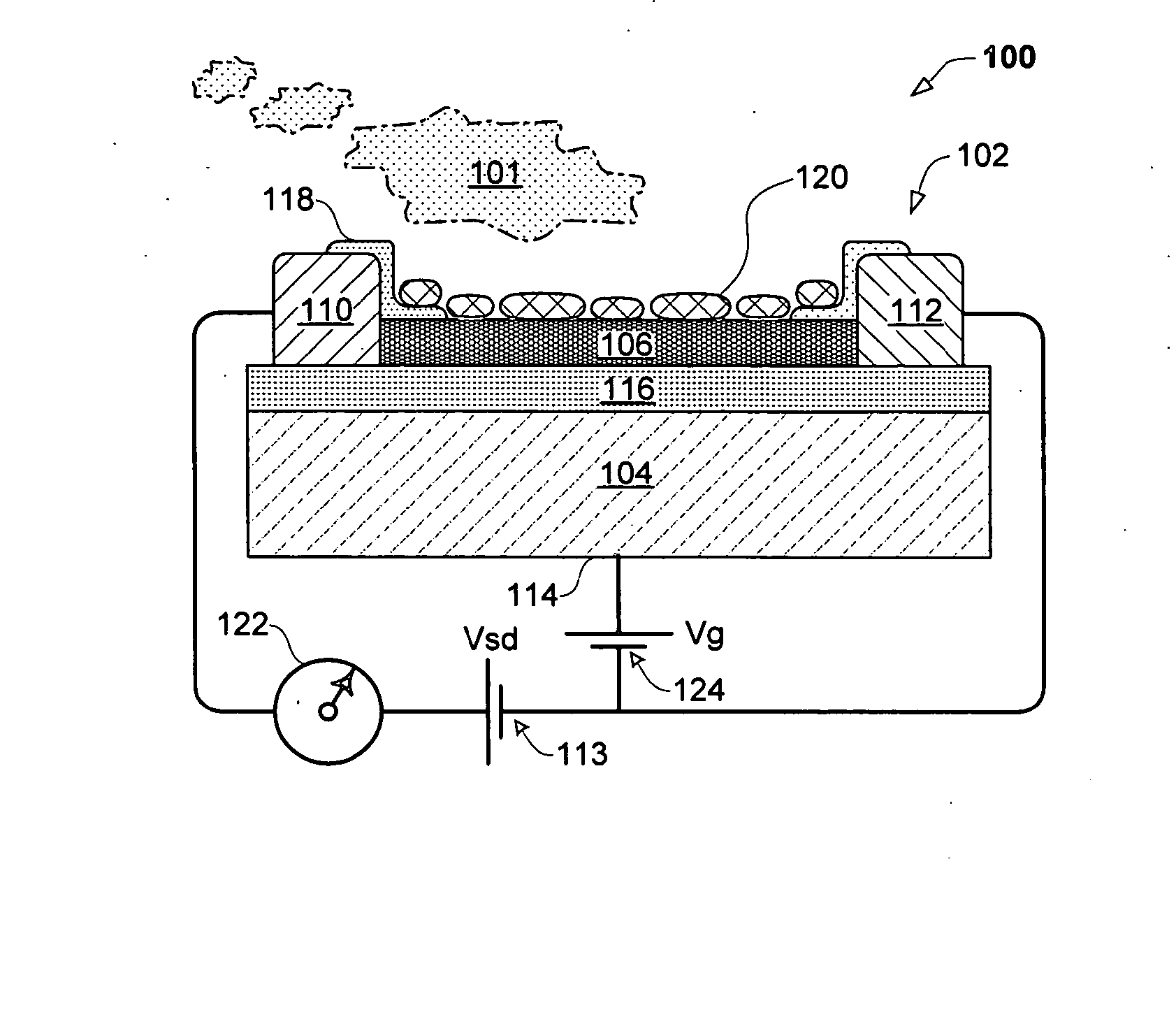
[0091]FIG. 1. shows an exemplary electronic sensing device 100 having aspects of the invention, for detecting an analyte 101 (e.g., inorganic species such as NH3, CO2, H2S, NO and the like; organic compounds such as glucose, ethanol and the like; biomolecules such as DNA, globular proteins and the like). A number of alternative sensor device architectures and operating modes are possible, and may be employed alone or in combinations without departing from the spirit of the invention. In the example of FIG. 1, sensing device 100 includes a nanostructure sensor 102 configured for convenient transconductance measurements, as well as other properties. Sensor 102 comprises a substrate 104.

[0092] Sensor 102 comprises a conductive (e.g., semiconductive) nanostructured element configured to include a channel, coating or layer 106 and comprising a nanostructured material (e.g., one or more conducting or semiconducting nanotubes, nanorods, nanowires and / or...


PUM

PropertyMeasurementUnit
currentaaaaaaaaaa
thickaaaaaaaaaa
thickaaaaaaaaaa

Abstract

Embodiments of nanoelectronic sensors are described, including sensors for detecting analytes such ammonia. An environmental control system employing nanoelectronic sensors is described. A personnel safety system configured as a disposable badge employing nanoelectronic sensors is described. A method of dynamic sampling and exposure of a sensor providing a number of operational advantages is described.

Description

CROSS-REFERENCE TO RELATED APPLICATION [0001] This application claims priority pursuant to 35 USC. § 119(e) to the following US Provisional Applications, each of which applications are incorporated by reference: [0002] No. 60 / 748,834 filed Dec. 9, 2005 entitled “Nanoelectronic Sensors Having Substrates With Pre-Patterned Electrodes, And Environmental Ammonia Control System”. [0003] This application is a continuation-in-part of and claims priority to U.S. patent application Ser. No. 11 / 588,845, filed Oct. 26, 2006 (Attorney Docket No. 612, 407-098; published 2006-______), entitled “Anesthesia Monitor, Capacitance Nanosensors and Dynamic Sensor Sampling Method”, which is incorporated by reference; and which in turn claims the priority to the following US provisional and non-provisional patent applications, each of which applications are incorporated by reference: [0004] No. 11 / 488,456 filed Jul. 18, 2006 (published 2006-______) entitled “Improved Carbon Dioxide Nanosensor, And Respira...

Claims


Application Information

Patent Timeline
24 Apr 2008
Publication
US20080093226A1
IPC
G01N27/26; G01N27/28; G01N27/30; G01N27/416
CPC
G01N27/127; G01N27/4146; G01N33/0054; H01L29/0669; Y10S977/957; B82Y15/00; Y02A50/20; G01N33/0068
Inventors
BRIMAN, MIKHAIL; BRYANT, CRAIG