Projection System with Compensation of Intensity Variations and Compensation Element Therefor

a projection system and intensity variation technology, applied in the field of projection systems with intensity variation compensation and compensation elements therefor, can solve the problems of non-uniform intensity distribution, problem area may occur, non-uniform intensity over field and pupil, etc., and achieve low refractive index, great modulation of layer thickness, and high refractive index

Inactive Publication Date: 2008-04-24
CARL ZEISS SMT GMBH
View PDF17 Cites 19 Cited by
  • Summary
  • Abstract
  • Description
  • Claims
  • Application Information

AI Technical Summary

Benefits of technology

[0028] The spatial distribution of the regions having a better and poorer reflection or transmission effect can be adapted to the spatial intensity distribution of the impinging radiation in any suitable manner in order to achieve the desired compensation effect. In this case, the modulation of the transmittance and/or reflectance may be for example rotationally symmetrical with respect to an optical axis of the optical component. It is also possible for the reflectance and/or transmittance of the interference layer system to have an azimuthal modulation with regard to the optical axis, in particular a radially symmetrical modulation with 2-, 3-, 4- or 6-fold symmetry. Such embodiments may be particularly useful in order to compensate for intensity modulations that result on account of intrinsic birefringence of crystal materials with specific crystal directions. It is also possible for an interference layer system to have a nonsymmetrical spatial modulation of its optical effect, for example a profile with a continuously rising or falling transmittance and/or reflectance in the transverse direction with respect to the optical axis or an arbitrary other distribution of regions of impaired efficiency.
[0029] In order to obtain a compensation effect that is as

Problems solved by technology

Especially in systems that operate with polarized light, reflectivity or transmission properties of interference layer systems that are dependent on the angle of incidence may lead to nonuniformities of the intensity over field and pupil.
This problem area may occur in the case of purely refractive (dioptric) imaging systems.
Finally, material defects, e.g. scattering centers or striations in t

Method used


Image

  • Projection System with Compensation of Intensity Variations and Compensation Element Therefor
  • Projection System with Compensation of Intensity Variations and Compensation Element Therefor
  • Projection System with Compensation of Intensity Variations and Compensation Element Therefor

Examples


Embodiment Construction

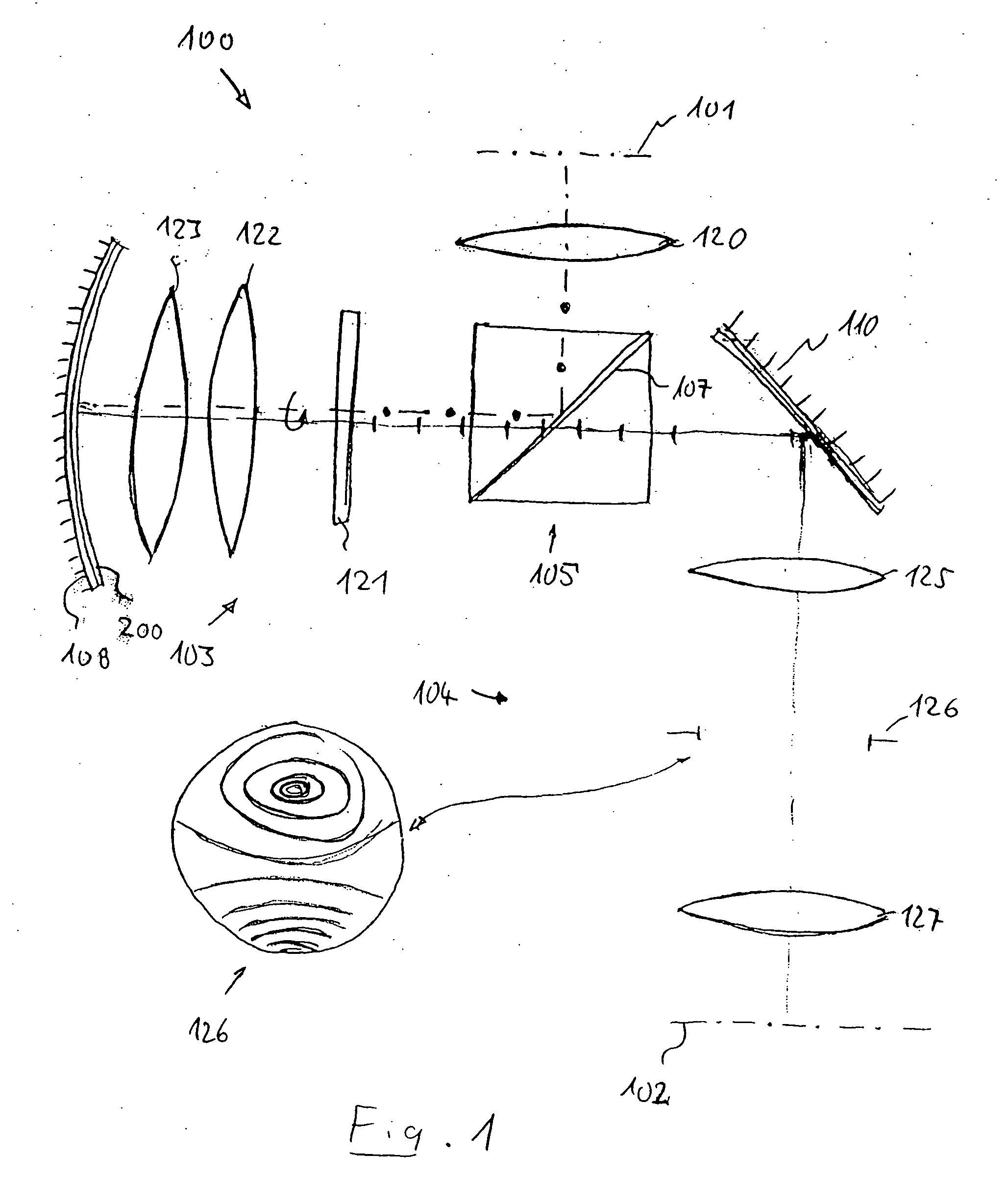
[0060] In order to elucidate a problem that can be solved by means of the invention, FIG. 1 schematically shows the construction of a catadioptric projection objective 100 with a polarization beam splitter. It serves for imaging a pattern of a reticle or the like arranged in its object plane 101 into its image plane 102 on a reduced scale, for example with the ratio 4:1, with exactly one real intermediate image (not shown) being generated. The projection objective, which is designed for an operating wavelength of λ=157 nm, has, between the object plane and the image plane, a first, catadioptric objective part 103 and behind that a second, purely dioptric objective part 104. The catadioptric objective part comprises a physical beam splitter 105 with a planar polarization beam splitter surface 107 oriented obliquely with respect to the optical axis, and also a mirror group with an imaging concave mirror 108. The objective part 104, which has a demagnifying effect, has a planar deflect...


PUM


Abstract

In a projection objective for imaging a pattern arranged in the object plane of the projection objective into the image plane of the projection objective, at least one optical component is provided which has a substrate in which at least one substrate surface is covered with an interference layer system having a great spatial modulation of the reflectance and/or of the transmittance over a usable cross section of the optical component, the modulation being adapted to a spatial transmission distribution of the remaining components of the projection objective in such a way that an intensity distribution of the radiation that is measured in a pupil surface has a substantially reduced spatial modulation in comparison with a projection objective without the interference layer system.

Description

BACKGROUND OF THE INVENTION [0001] 1. Field of the Invention [0002] The invention relates generally to projection systems with compensation of intensity variations and compensation elements therefor. [0003] The invention also relates to a projection objective for imaging a pattern arranged in the object plane of the projection objective into the image plane of the projection objective, and to an optical component having a substrate in which at least one substrate surface is covered with an interference layer system. The optical component may be provided in particular for incorporation into a catadioptric or dioptric projection objective or be incorporated into the latter. [0004] The invention also concerns a projection exposure apparatus, in particular for immersion lithography, such as is specified in the US patent applications bearing the official identification 60 / 592,208, 60 / 530,978, 60 / 591,775 or 60 / 612,823, which were not published before the priority date. The immersion mediu...

Claims


Application Information

Patent Timeline
IPC IPC(8): G03B27/72G03B27/54G02B5/28G02B13/02G02B17/08G03F7/20
CPCG02B13/02G03F7/70308G02B17/0892G02B17/0812G03F7/70133G03B27/547G03B27/725H01L21/0274
Inventor SCHEIBLE, PATRICKPAZIDIS, ALEXANDRAGARREIS, REINERTOTZECK, MICHAELFELDMANN, HEIKOGRAEUPNER, PAULROSTALSKI, HANS-JUERGENSINGER, WOLFGANG
Owner CARL ZEISS SMT GMBH
Why Eureka
Try Eureka