
Solid Oxide Type Fuel Battery Cell and Process for Producing the Same

a fuel battery and solid oxide technology, applied in the field of solid oxide fuel cell cells, can solve the problems of increasing the limit of the three-phase interface, difficult to control the shape of the liquid component, and difficult to control the shape of the pores after burning, and achieve the effect of small conductivity reduction of the electrolyte layer

Inactive Publication Date: 2008-05-01
THE TOKYO ELECTRIC POWER CO INC
View PDF4 Cites 33 Cited by
  • Summary
  • Abstract
  • Description
  • Claims
  • Application Information

AI Technical Summary

Benefits of technology

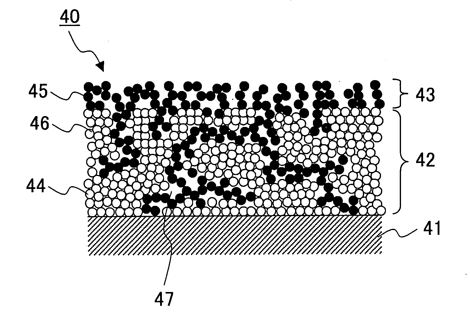
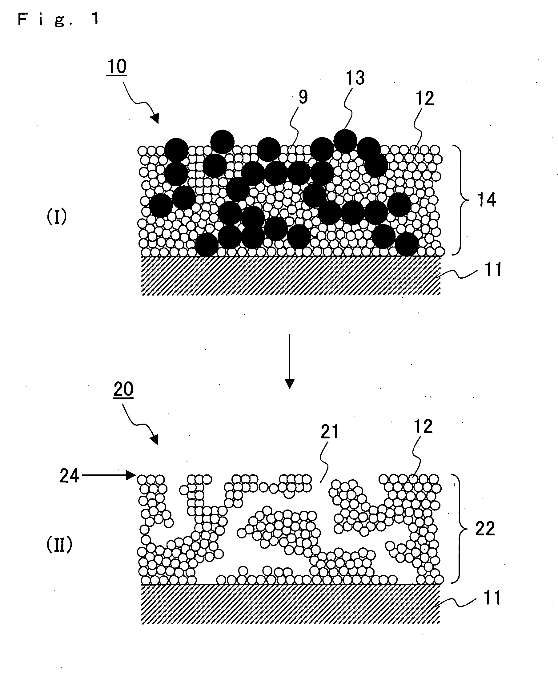
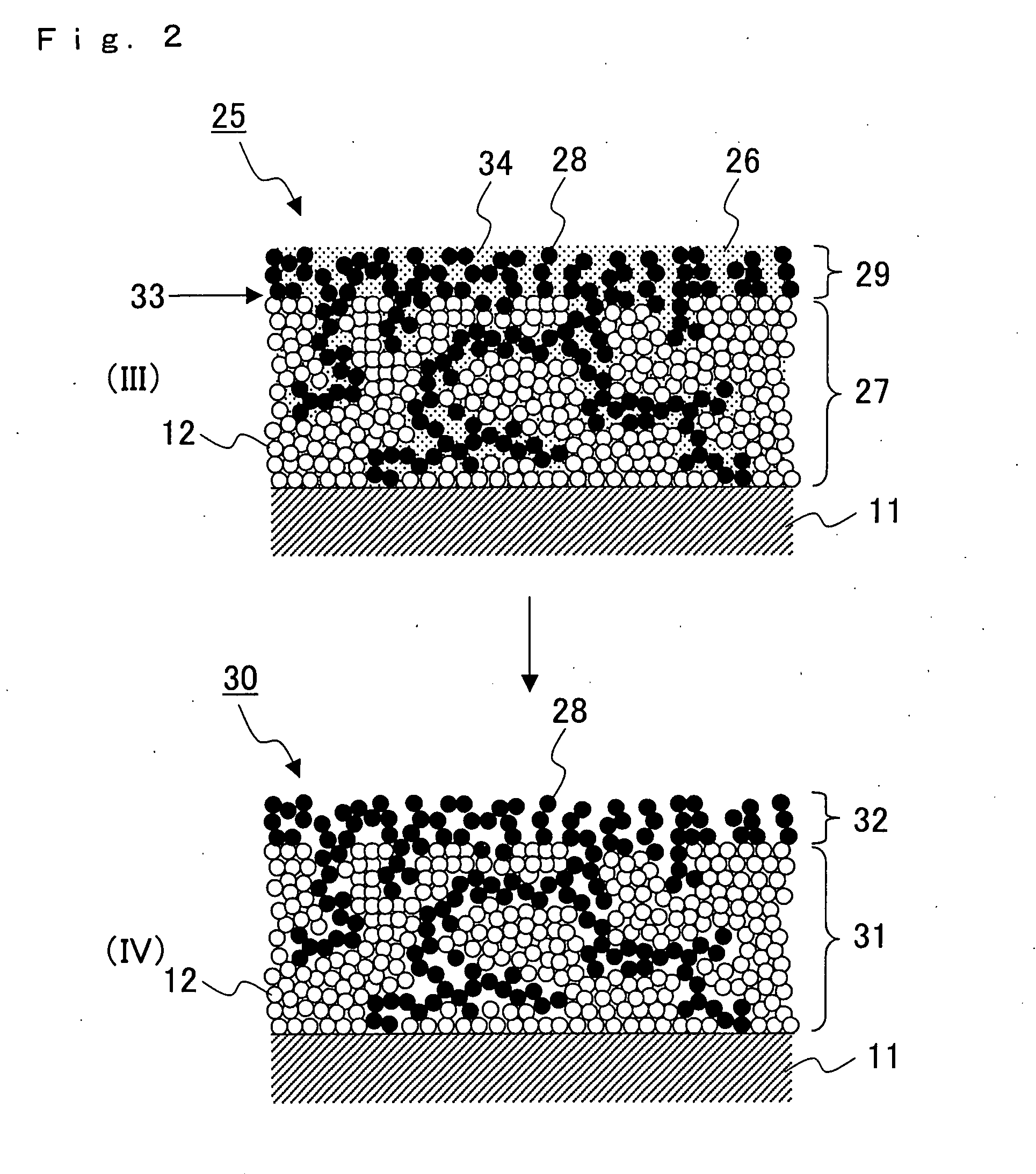
[0010]As a result of extensive research in order to achieve the above object, the present inventors have found that (1) if a solid pore-forming agent is added to a slurry for forming a porous electrolyte layer, it is possible to control the shape of the pores in the porous electrolyte layer, specifically, since the pore-forming agent is present in the clearance between the particles of electrolyte substance powder in the slurry and therefore, the size of the clearance is not smaller than the particle size of the pore-forming agent, the clearance between the particles of electrolyte substance powder, that is, the pore diameter after burning, can be greater than the diameter of the pore-forming agent. For this reason, pores having a diameter sufficiently large for an electrode substance to be filled therein can be surely formed, which ensures only a small decrease in the conductivity of the porous electrolyte layer and an increase in the amount of the three-phase interface. The inventors have further found that (2) if the average particle diameter of the electrolyte substance powder is smaller than the average particle diameter of the said pore-forming agent, the contact area of the electrolyte substance powder can be increased and the particles of the electrolyte substance powder can be more easily sintered among themselves, which results in an increase in the conductivity of the porous electrolyte layer.
[0014]According to the present invention, a process for producing a cell for solid oxide fuel cells which can increase the three-phase interface of the porous electrolyte layer and exhibits only a small conductivity reduction of the electrolyte layer can be obtained.

Problems solved by technology

However, there is naturally a limit to the amount of the three-phase interface increased by decreasing the particle size of the mother particles and the child particles.
It was difficult to control the shape of the liquid component in the slurry due to its liquid properties, that is, it was difficult to control the shape of the pores after burning.
However, a large proportion of the liquid component in the slurry increases the pore volume of the electrolyte layer and decreases the amount of the electrolyte substance powder in the electrolyte layer, resulting in a decrease of passages in which electrons move, which in turn decreases conductivity of the electrolyte layer.
Lowered conductivity leads to a low output of the fuel cell.

Method used


Image

  • Solid Oxide Type Fuel Battery Cell and Process for Producing the Same
  • Solid Oxide Type Fuel Battery Cell and Process for Producing the Same
  • Solid Oxide Type Fuel Battery Cell and Process for Producing the Same

Examples


example 1

Preparation of Fuel Electrode Layer

(Preparation of Slurry for Forming Fuel Electrode Layer)

[0102]55 g of nickel oxide (NiO), 45 g of scandia ceria-stabilized zirconia (10Sc1CeSZ), 10 ml of di-n-butyl phthalate, 2 ml of octyl phenyl ether, 2 ml of a dispersant (“Nonion OP-83RAT” manufactured by NOF Corp.), 10 g of polyvinyl butyral resin (manufactured by Wako Pure Chemical Industries, Ltd.), 80 ml of isopropanol, and 80 ml of acetone were added to a ball mill, and mixed at room temperature for 24 hours. The solvent was evaporated from the resulting slurry using an evaporator under reduced pressure to make the viscosity of the slurry 10,000 mPa·s, thereby obtaining a slurry A for forming a fuel electrode.

[0103]Nickel oxide (average particle diameter: 7 micrometers)

[0104]Scandia ceria-stabilized zirconia (scandia content in zirconia: 10 mol %, ceria content in zirconia: 1 mol %, average particle diameter: 0.55 micrometers)

(Baking of Slurry for Forming a Fuel Electrode Layer)

[0105]A slu...

example 2

[0125]Preparation of a fuel electrode, preparation of an electrolyte substrate, formation of a porous electrolyte layer, and formation of an air electrode layer were carried out in the same manner as in Example 1, except for using 100 g of lanthanum strontium manganate instead of 82 g of lanthanum strontium manganate and 18 g of scandia ceria-stabilized zirconia used in the preparation of the slurry for fuel electrode layer to obtain a cell for solid oxide fuel cells J. The volume ratios of the scandia ceria-stabilized zirconia and lanthanum strontium manganate to the apparent volume of the air electrode substance-filled porous electrolyte layer in the air electrode substance-filled porous electrolyte layer of the cell for solid oxide fuel cells J were respectively 56% and 12%.

Performance Evaluation

[0126]The same experiment as in Example 1 was carried out except for using the slurry for forming an air electrode used in Example 2 instead of the slurry for forming an air electrode G. ...


PUM


Abstract

A process for producing a cell for solid oxide fuel cells comprising a porous electrolyte layer-forming step of obtaining an electrolyte substrate in which a porous electrolyte layer is formed by applying a slurry for forming an electrolyte layer containing an electrolyte substance powder and a pore-forming agent to the surface of an electrolyte substrate and burning the electrolyte substrate, and an electrode layer-forming step of obtaining an electrolyte substrate in which an electrode substance-filled porous electrolyte layer and an electrode layer are formed by applying a slurry for forming an electrode containing an electrode substance powder, a mixture of an electrode substance powder and an electrolyte substance powder, or a composite material powder of an electrode substance and an electrolyte substance, onto the surface of the porous electrolyte layer of the electrolyte substrate on which the porous electrolyte layer is formed, and burning the electrolyte substrate in which the porous electrolyte layer is formed. According to the present invention, a process for producing a cell for solid oxide fuel cells which can increase the three-phase interface of the porous electrolyte layer and exhibits only a small conductivity reduction of the electrolyte layer can be obtained.

Description

TECHNICAL FIELD[0001]The present invention relates to a cell for solid oxide fuel cells and a process for producing the same.BACKGROUND ART[0002]A cell of a solid oxide fuel cell has an electrolyte sandwiched by a fuel electrode and an air electrode. The electrolyte, fuel electrode, and air electrode are formed of a metal oxide or a metal. Thus, the cell is entirely a solid.[0003]In the solid oxide fuel cell, a cell reaction occurs in a three-phase interface in which all of the gases, the ions, and the electrons are reactive. For this reason, the three-phase interface area must be increased in order to promote cell performance.[0004]Conventionally, a method of increasing the three-phase interface area by mixing an electrolyte substance with an electrode substance, and further forming an electrode with a porous structure has been used. In this method, the three-phase interface is increased by increasing not only the contact area of the electrolyte substance with the electrode substan...

Claims


Application Information

Patent Timeline
IPC IPC(8): H01M8/10B05D1/00
CPCH01M8/124H01M2300/0068Y02E60/525Y02E60/521H01M2300/0094Y02E60/50Y02P70/50
Inventor SHIMADA, HIROYUKI
Owner THE TOKYO ELECTRIC POWER CO INC
Learn More