

Multi-bed selective catalytic reduction system and method for reducing nitrogen oxides emissions
a catalytic reduction and selective catalytic technology, applied in the field of systems and methods for reducing nitrogen oxides (nox) emissions, can solve the problems of difficult to meet current regulations regarding ammonia slip in vehicle exhaust systems, limited ammonia use practicability, and inability to use the technology in automobiles and other mobile engines
- Summary
- Abstract
- Description
- Claims
- Application Information
AI Technical Summary
Benefits of technology
Problems solved by technology
Method used
Image

Examples
example 1
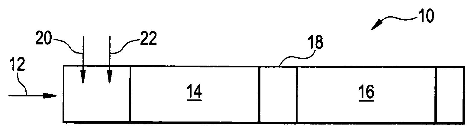
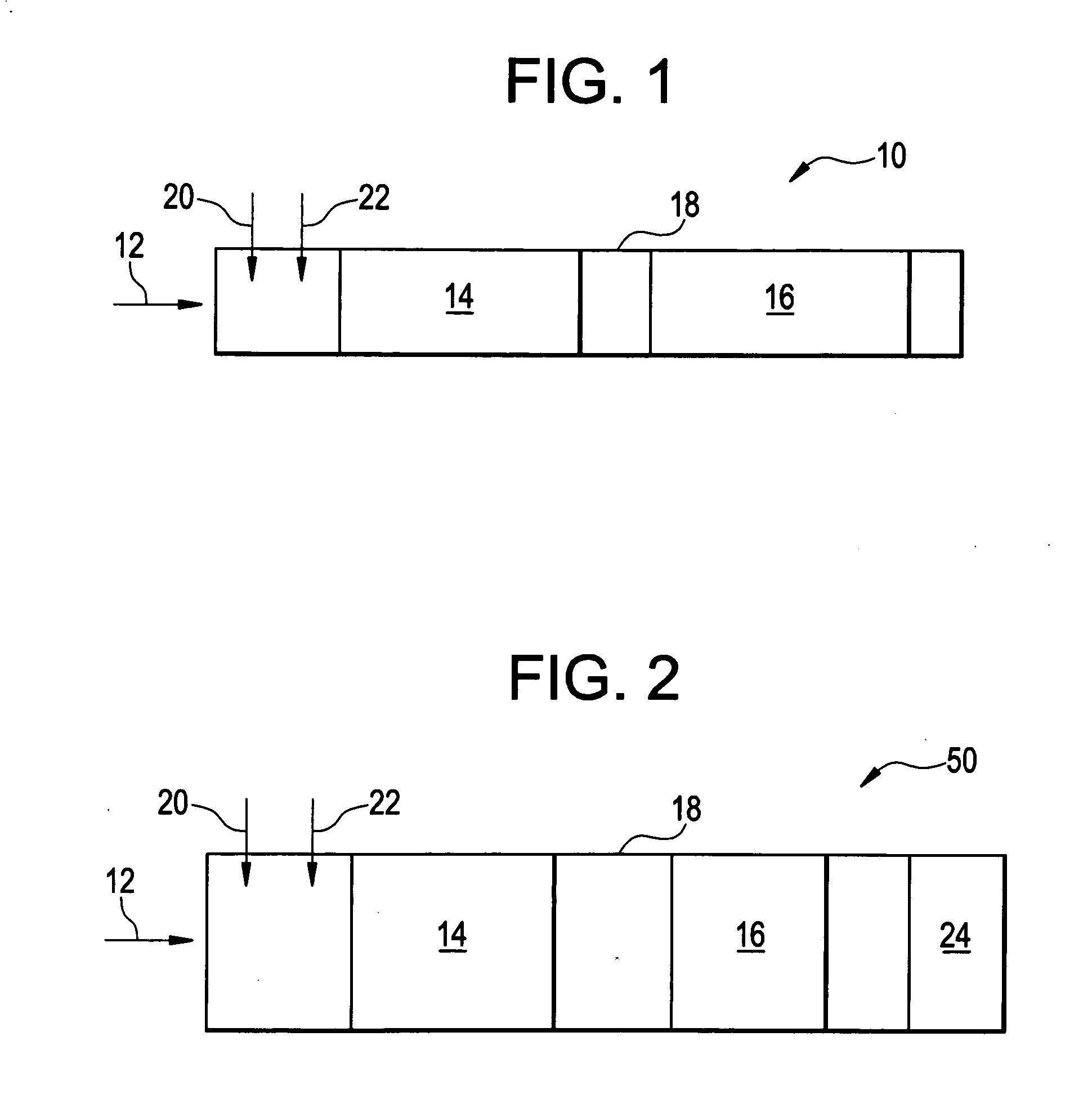
[0034]In this example, the percent nitrogen oxide conversion was measured in a multi-bed system that included injection of ethanol as a reductant and hydrogen gas (H2) as a co-reductant in the presence of SO2. The percent conversion was compared to a single HC—SCR bed system as well as a multi-bed system with ethanol only, with ethanol and SO2, and inn the single bed system with ethanol, SO2 and H2 injection. The multi-bed system included the HC—SCR bed in fluid communication with a NH3—SCR bed. The HC—SCR bed included a gallium-silver catalyst deposited onto gamma aluminum. The NH3—SCR was commercially obtained from Cormetech, Inc. The inlet concentration of NOx was 650 ppm, wherein the concentration of reductant (ethanol only) needed to drive the conversion above 75% was determined to be 900 ppm. For these experiments, SO2 was injected at 10 ppm, and H2 was at 4,000. In addition to the inlet concentration of NOx at 650 ppm, the exhaust gas consisted of oxygen, gas at 12%, water at...
example 2
[0036]In this example, the effect of sulfur dioxide on the performance of the HC—SCR / NH3—SCR multi-bed was monitored. The HC—SCR catalyst was formed of gallium and silver as previously described in the example above whereas the NH3—SCR catalyst was V2O5—TiO2—W2O5. The inlet concentration of NOx was 630 ppm, wherein the concentration of reductant (ethanol only) was 900 ppm. In addition to the inlet concentration of NOx, the exhaust gas consisted of oxygen gas at 12%, water at 7% with the balance being nitrogen. For these experiments, SO2 concentration was varied in the absence of hydrogen gas. Temperature was maintained at 450° C. and SV was at 40,000 hr−1. The results for the varying concentrations of sulfur dioxide are provided in Table 2 below.
TABLE 2HC—SCR + (V2O5—TiO2—W2O5)NOx ConversionConversion to N2SO2 (ppm)(%)(%)4857687670127266206558
[0037]The results clearly show that the percentages of NOx conversion and N2 conversion directly depended on the amount of sulfur dioxide pres...
example 3
[0038]In this example, the effect of hydrogen gas (H2) on the performance of the HC—SCR / NH3—SCR multi-bed of Example 2 was examined. The exhaust feed was in accordance with that detailed in Example 2 and further included 5 ppm SO2. The amount of hydrogen injected varied, the results of which are provided in Table 3.
TABLE 3HC—SCR + (V2O5—TiO2—W2O5)H2 (ppm)NOx ConversionConversion to N20686010008368200085694000927280009580
[0039]The results clearly show an increase in NOx conversion and conversion to N2 as the amount of hydrogen gas was increased as the co-reductant. Moreover, the use of hydrogen gas as a co-reductant in the exhaust fluid minimized sulfur dioxide deactivation of the catalyst materials.
PUM
| Property | Measurement | Unit |
|---|---|---|
| Temperature | aaaaa | aaaaa |
| Temperature | aaaaa | aaaaa |
| Fraction | aaaaa | aaaaa |
Abstract
Description
Claims
Application Information