Method to reduce mechanical wear of immersion lithography apparatus

a technology of immersion lithography and mechanical wear, which is applied in the field of integrated circuit manufacturing, can solve the problems of reduced yield performance, similar fracture points, and fracture points which may wear and generate particles, and achieve the effect of reducing defects

Inactive Publication Date: 2008-06-12
IBM CORP
View PDF7 Cites 16 Cited by
  • Summary
  • Abstract
  • Description
  • Claims
  • Application Information

AI Technical Summary

Benefits of technology

[0011]Bearing in mind the problems and deficiencies of the prior art, it is therefore an object of the present invention to provide components of an immersion lithography system that will minimize defects due to mechanical wear.

Problems solved by technology

Particles, chemical contaminants or bacteria are undesirable as they can potentially deposit onto the surface of the wafer 3 causing defects.
One of the primary challenges with immersion lithography is reducing defects.
Particles deposited on the imaging surface during the scanning process can lead to reduced yield performance.
To reduce the mechanical wear sharp edges of these elements may be defined or chamfered, however, mechanical polishing to create the defined edge can create fracture points which may wear and generate particles after repetitive use.
Mechanical polishing of surfaces to attain nanometer-scale flatness may also induce similar fracture points.
Quartz closing disks are particularly susceptible to damage by mechanical abrasion due to their moderate hardness (Moh hardness value of 7).
Closing disks made from other ceramic materials, such as Zerodur® (from SCHOTT Corporation), may improve on the quartz with regards to hardness but their benefits in terms of defect reduction are unproven.
Common coatings utilized in the field of optics, such as oxides or fluorides, however, cannot be utilized since they tend to be brittle and are easily damaged.

Method used


Image

  • Method to reduce mechanical wear of immersion lithography apparatus
  • Method to reduce mechanical wear of immersion lithography apparatus
  • Method to reduce mechanical wear of immersion lithography apparatus

Examples


Embodiment Construction

[0025]The present invention will now be described in greater detail by referring to the following discussion with reference to the drawings that accompany the present application. It is observed that the drawings of the present application are provided for illustrative purposes and thus they are not drawn to scale.

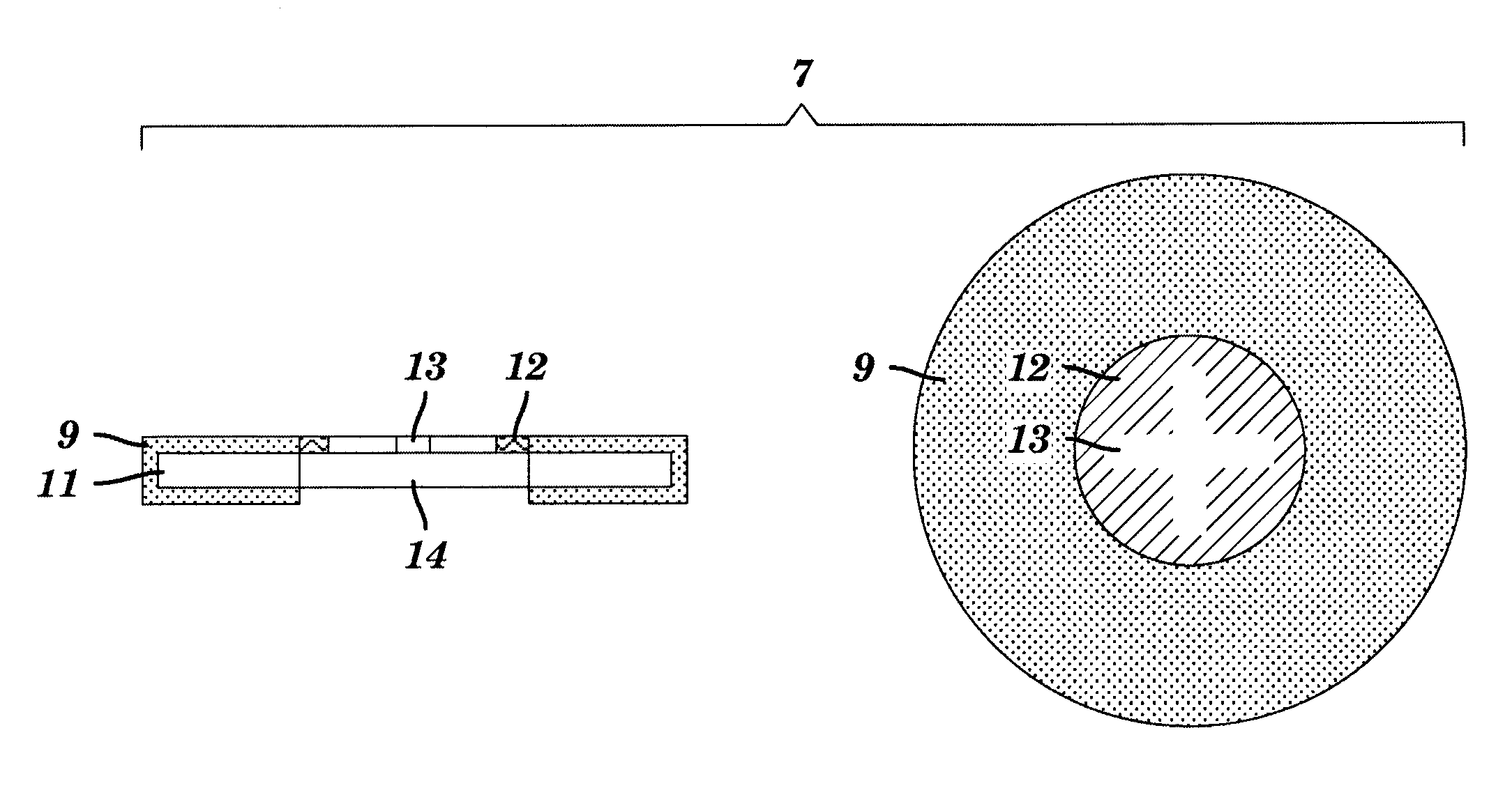
[0026]In accordance with the present invention, a thin, protective, single- or multi-layer coating is provided on the surface of components of an immersion lithography scanner, in particular, where such components may contact other components as well as contact the immersion fluid. For example, the protective coating may be provided on a showerhead, the closing disk or the closing disk receptacle in the wafer stage to reduce wear of the components due to mechanical contact during operation.

[0027]The protective coating is preferably sufficiently thin so as to maintain the surface finish, flatness and mechanical tolerances of components, such as between a closing disk and th...


PUM

PropertyMeasurementUnit
thicknessaaaaaaaaaa
surface roughnessaaaaaaaaaa
Young's modulusaaaaaaaaaa

Abstract

A protective coating is provided for components of an immersion lithography tool, in which at least a portion of a component exposed to the immersion fluid is protected by a thin, hard protective coating, comprising materials such as silicon carbide, diamond, diamond-like carbon, boron nitride, boron carbide, tungsten carbide, aluminum oxide, sapphire, titanium nitride, titanium carbonitride, titanium aluminum nitride and titanium carbide. The protective coating may be formed by methods such as CVD, PECVD, APCVD, LPCVD, LECVD, PVD, thin-film evaporation, sputtering, and thermal annealing in the presence of a gas. The protective coating preferably has a hardness greater than a Knoop hardness of about 1000 and more preferably greater than about 2000, or a Moh hardness greater than about 7, more preferably greater than about 9. The protective coating minimizes defects due to mechanical wear of scanner components.

Description

FIELD OF THE INVENTION[0001]The present invention relates to the manufacture of integrated circuits and an apparatus and method for reducing defects and improving durability of equipment used in the manufacture of integrated circuits. More particularly, the present invention relates to an apparatus and method for reducing mechanical wear of components in an immersion lithography apparatus.BACKGROUND OF THE INVENTION[0002]Liquid immersion lithography has emerged as the leading candidate for sub-wavelength, optical patterning of advanced integrated circuits. By filling the gap between the last lens element of the optical projection system and the surface of the wafer with a high refractive index fluid, optical projection systems having numerical aperture (NA) approaching the refractive index of the fluid are possible. High numerical aperture enables increased resolution which is essential for improving performance of integrated circuits. The high refractive index fluid used in this ma...

Claims


Application Information

Patent Timeline
Patent Type & Authority Applications(United States)
IPC IPC(8): B32B9/00
CPCC23C30/00G03F7/7095G03F7/70916G03F7/70341
Inventor PATEL, KAUSHAL S.CORLISS, DANIEL A.
Owner IBM CORP
Why Eureka
Try Eureka