Spreading layer and humidity control layer for enhancing sensor performance

a technology of humidity control and spreading layer, applied in the field of improved optical sensors, can solve the problems of increasing costs and limiting the shelf life of sensors, and achieve the effect of increasing costs and complicating cassette design

Active Publication Date: 2008-06-26
OPTI MEDICAL SYST
View PDF7 Cites 15 Cited by
  • Summary
  • Abstract
  • Description
  • Claims
  • Application Information

AI Technical Summary

Benefits of technology

[0003]It is known that a key element for achieving laboratory-grade precision and accuracy is the use of an aqueous-based calibration solution containing known concentrations of all analytes to be tested. Typically, a single point calibration is performed immediately prior to the measurement of a clinical sample. This ensures reproducible results from instrument-to-instrument and from sensor-to-sensor. The current sensor or “optode” cassettes used in certain optical sensor based instruments, such a

Problems solved by technology

The principal disadvantage for wet-storage is the resulting sensor “shelf-life” limitation, especially for certain sensors such as biosensors with hydrolytically

Method used


Image

  • Spreading layer and humidity control layer for enhancing sensor performance
  • Spreading layer and humidity control layer for enhancing sensor performance
  • Spreading layer and humidity control layer for enhancing sensor performance

Examples


example 1

[0039]One embodiment of the present invention, a sodium sensor, is described as follows. Such sensors are prepared as described further below.

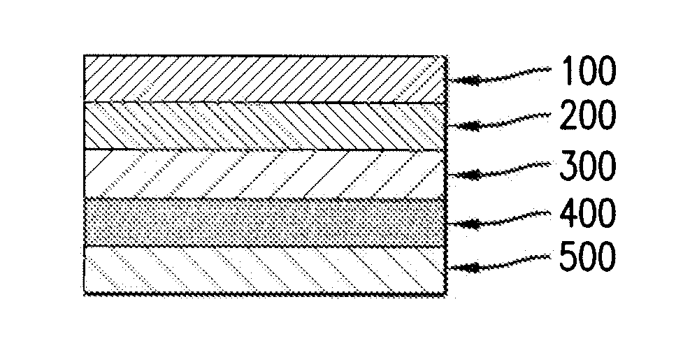
[0040]0.5 g cellulose powder (25 μm sieved) with immobilized indicator (U.S. Pat. No. 5,952,491, the entire disclosure of which is incorporated by reference herein) was suspended in 9.5 g 10% (w / w) D4 hydrogel in 90% (w / w) ethanol-water for 16 h. The resulting homogeneous dispersion was coated onto a polyester foil (8.5″×11″ sheet) to a final dry thickness of 10 μm to form the Indicator layer as shown in FIG. 1. The Indicator layer was then coated with a dispersion consisting of 0.3 g carbon black suspended in 9.7 g 10% (w / w) D4 hydrogel in 90% (w / w) ethanol-water to a dry thickness of 5 μm to form an Overcoat layer. The Overcoat layer was then coated with a Humidity Control layer containing 0.5 g cellulose (10 μm), 1.0 g PVP and 8.5 g 10% (w / w) D4 hydrogel in 90% (w / w) ethanol-water to a dry thickness of 50 μm. The Humidity Control layer was ...

example 2

[0041]One embodiment for an optical chloride sensor, according to the present invention, is prepared as described below.

[0042]1.5 g of immobilized chloride indicator (U.S. Pat. No. 6,613,282, the entire disclosure of which is incorporated by reference herein) was suspended in 8.5 g of 10% (w / w) D4 hydrogel in 90% (w / w) ethanol-water for 16 h. The resulting homogeneous dispersion was coated onto a polyester film (8.5″×11″ sheet) to a final dry thickness of 10 μm to form the Indicator layer as shown in FIG. 1. The Indicator layer was then coated with 0.3 g carbon black suspended in 9.7 g 10% (w / w) D4 hydrogel in 90% (w / w) ethanol-water to a dry thickness of 5 μm to form an Overcoat layer. The Overcoat layer was then coated with a solution containing 0.3 g cellulose (15 μm), 0.5 g polyvinyl pyrrolidone (PVP) and 9.2 g 10% (w / w) D4 hydrogel in 90% (w / w) ethanol-water to a dry thickness of 20 μm to form the Humidity Control layer. The Humidity Control layer was then coated with a solutio...

example 3

[0043]One embodiment for an optical potassium sensor, according to the present invention, is prepared in the manner described further below.

[0044]0.5 g cellulose powder (10 μm sieved) with immobilized potassium indicator (U.S. Pat. No. 6,211,359, the entire disclosure of which is incorporated by reference herein) was suspended in 9.5 g of 10% (w / w) D4 hydrogel in 90% (w / w) ethanol-water for 16 h. The resulting homogeneous dispersion was coated onto a polyester film (8.5″×11″ sheet) to a final dry thickness of 10 μm to form the Indicator layer as shown in FIG. 1. The indicator layer was then coated with 0.3 g carbon black suspended in 9.7 g 10% (w / w) D4 hydrogel in 90% (w / w) ethanol-water to a dry thickness of 5 μm to form an Overcoat layer. The overcoat layer was then coated with a solution containing 0.7 g cellulose (20 μm), 1.5 g polyvinyl pyrrolidone (PVP) in 7.8 g 10% (w / w) D4 hydrogel in 90% (w / w) ethanol-water to a dry thickness of 40 μm to form the Humidity Control layer. The...


PUM

PropertyMeasurementUnit
Thicknessaaaaaaaaaa
Thicknessaaaaaaaaaa
Thicknessaaaaaaaaaa

Abstract

The invention is directed to optical sensors for measuring clinically relevant analytes, their methods of manufacture, and their various uses. In an effort to develop a dry calibration method for the optical sensors of the invention it is discovered that water content inside or in the immediate vicinity of a such a sensor can have a major impact on fluorescence intensity (i.e., a sensor's response in the dry state). Thus, one of the objectives of the invention is the elimination of the bias of sensor responses measured at different humidity environments.

Description

[0001]This application claims the benefit of U.S. Provisional Patent Application No. 60 / 869,268, which was filed on Dec. 8, 2006, and is incorporated by reference in its entirety as if fully set forth herein.FIELD OF THE INVENTION[0002]The invention is directed to improved optical sensors for measuring clinically relevant analytes, their methods of manufacture, and their various uses. Typically, for performing an accurate measurement, a calibration step is required for eliminating sensor to sensor and instrument to instrument variations. Conventional “wet” calibration methods require that a calibration step be carried out with a calibration liquid that contains a known concentration of analyte. However, the calibration method of choice for an optical sensor to which the invention is directed is a “dry calibration” method. In a dry calibration method, fluorescence intensity of a sensor in a “dry” state (i.e., right out of the packaging) is measured. The sensor's response in the dry s...

Claims


Application Information

Patent Timeline
IPC IPC(8): B32B9/04B05D5/00B32B3/10
CPCB01D2253/202B01D2257/80B01J20/28033B01J20/28097G01N21/274Y10T428/265G01N21/8483G01N33/525G01N2021/7786Y10T428/24273G01N21/6428Y10T428/31504
Inventor RAMAMURTHY, NARAYANANHE, HUARUILIN, CHAO
Owner OPTI MEDICAL SYST
Why Eureka
Try Eureka