Asymmetric electrochemical supercapacitor and method of manufacture thereof

a supercapacitor and electrochemical technology, applied in the field of asymmetric electrochemical supercapacitors, can solve the problems of high power density of supercapacitors, low energy density when compared to batteries, and high cost of supercapacitors, so as to improve power density, improve power density, and improve the effect of energy density

Inactive Publication Date: 2008-07-03
U S NANOCORP
View PDF31 Cites 88 Cited by
  • Summary
  • Abstract
  • Description
  • Claims
  • Application Information

AI Technical Summary

Benefits of technology

[0016]The asymmetric supercapacitors have improved energy density by electrically coupling a positive electrode of high faradaic capacity such a one comprising manganese dioxide (MnO2) with a negative electrode that stores charge through charge separation at the electric double-layer such as one comprising carbon. The asymmetric supercapacitors also improve power density by using high surface area nanostructured electrode materials.
[0017]The asymmetric supercapacitor offers other practical advantages in addition to higher energy density. For example, its capacitance is lower than that of a double layer capacitor. In particular, the capacitance of the asy

Problems solved by technology

Supercapacitors possess very high power densities, but low energy densities when compared to batteries.
These systems operate at approximately 2.8 V. At its present state of development, energy density projections for practical devices are in the range from 6-10 Watt*hours/kilogram (Wh/kg) at power levels of about 2 kilowatts/kilogram (kW/kg), but long-term stability and cycle life remain unclear.
This approach requires use of very high purity materials and processes due to the high cell operating voltage, thus adding to the supercapacitor cost.
However, even with the doubling of energy density, ruthenium-based approaches are prohibiti

Method used


Image

  • Asymmetric electrochemical supercapacitor and method of manufacture thereof
  • Asymmetric electrochemical supercapacitor and method of manufacture thereof
  • Asymmetric electrochemical supercapacitor and method of manufacture thereof

Examples


examples

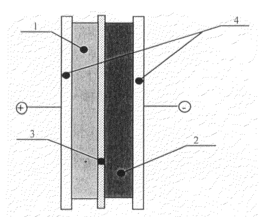
[0051]Supercapacitors were assembled comprising two electrodes on either side of a separator. Both electrodes had a current collector on the side opposite to the separator. Each circular electrode was 0.031 cm thick and 1.9 cm in diameter. The electrolyte was 32 wt % KOH. The separator was Celgard™ 3501. The current collectors comprised carbon black loaded PVC sheet material that was 50 micrometers thick. The particulate carbon was a natural carbon with a 5 micrometer particle size. The nenofiborous carbon was carbon fibers with a diameter of less than 100 nm. The particulate MnO2 was electrochemically formed material wherein the particles had a mean single linear dimension of less than 100 microns. The nanostructured MnO2 had a grain size less than 100 nm. The carbon and MnO2 were saturated with the electrolyte and then weighed. Table 1 shows the composition of each example as well as energy and capacitance data. Electrochemical impedance measurements were made on each example at 1...


PUM


Abstract

Asymmetric supercapacitors comprise: a positive electrode comprising a current collector and a first active material selected from the group consisting of manganese dioxide, silver oxide, iron sulfide, lithium manganese oxide, lithium cobalt oxide, lithium nickel oxide, lithium iron phosphate, and a combination comprising at least one of the foregoing active materials; a negative electrode comprising a carbonaceous active material; an aqueous electrolyte solution selected from the group consisting of aqueous solutions of hydroxides of alkali metals, aqueous solutions of carbonates of alkali metals, aqueous solutions of chlorides of alkali metals, aqueous solutions of sulfates of alkali metals, aqueous solutions of nitrates of alkali metals, and a combination comprising at least one of the foregoing aqueous solutions; and a separator plate. Alternatively, the electrolyte can be a non-aqueous ionic conducting electrolyte or a solid electrolyte.

Description

CROSS-REFERENCE TO RELATED APPLICATION[0001]This application is a continuation-in-part of, and claims priority to, U.S. patent application Ser. No. 09 / 590,496, filed Jun. 9, 2000, which is incorporated by reference herein in its entirety.STATEMENT OF GOVERNMENT INTEREST[0002]The invention was made with Government support under contract NAS 3-99054 awarded by the National Aeronautics and Space Agency. The Government has certain rights in the invention.FIELD OF THE INVENTION[0003]The present invention relates to electrochemical capacitors. In particular, the present invention relates to asymmetric electrochemical capacitors and methods to improve their energy density and power density.BRIEF DESCRIPTION OF THE RELATED ART[0004]Electrochemical capacitors (ECs) can store several hundred times more energy per unit weight (gravimetric energy density) and volume (volumetric energy density) than traditional electrolytic capacitors. Hereinafter energy density refers to both gravimetric and vo...

Claims


Application Information

Patent Timeline
IPC IPC(8): H01G9/038H01G9/042
CPCH01G11/36H01G11/32Y02E60/13H01G11/46
Inventor LIPKA, STEPHEN M.MILLER, JOHN R.XIAO, TONGSAN D.DAI, JINXIANG
Owner U S NANOCORP
Why Eureka
Try Eureka