Nanocomposite for fuel cell, method of preparing the nanocomposite, and fuel cell including the nanocomposite

a fuel cell and nanocomposite technology, applied in the field of carbon nanofibers, can solve the problems of uniform dispersion of catalysts in carbon supports, and achieve the effects of improving fuel cell efficiency, high surface oxygen content, and high electrochemical efficiency

Inactive Publication Date: 2008-07-24
SAMSUNG SDI CO LTD
View PDF9 Cites 15 Cited by
  • Summary
  • Abstract
  • Description
  • Claims
  • Application Information

AI Technical Summary

Benefits of technology

[0030]The nanocomposite according to the present invention has high surface oxygen content compared to conventional composite material, and metal catalyst nano particles are uniformly distributed on the outer walls of the carbon nanofiber in the nanocomposite, thereby having high electrochemical efficiency. Thus, efficiency of fuel cells can be improved using the nanocomposite.

Problems solved by technology

Recently, research has been conducted into fuel cells as power sources for vehicles and electronic devices due to increasing concerns regarding environmental problems in burning fossil fuels and exhaustion of natural resources.
However, the degree of dispersion of the catalyst is not uniform in the carbon support.

Method used


Image

  • Nanocomposite for fuel cell, method of preparing the nanocomposite, and fuel cell including the nanocomposite
  • Nanocomposite for fuel cell, method of preparing the nanocomposite, and fuel cell including the nanocomposite
  • Nanocomposite for fuel cell, method of preparing the nanocomposite, and fuel cell including the nanocomposite

Examples


example 1

Preparation of Carbon Nanofiber

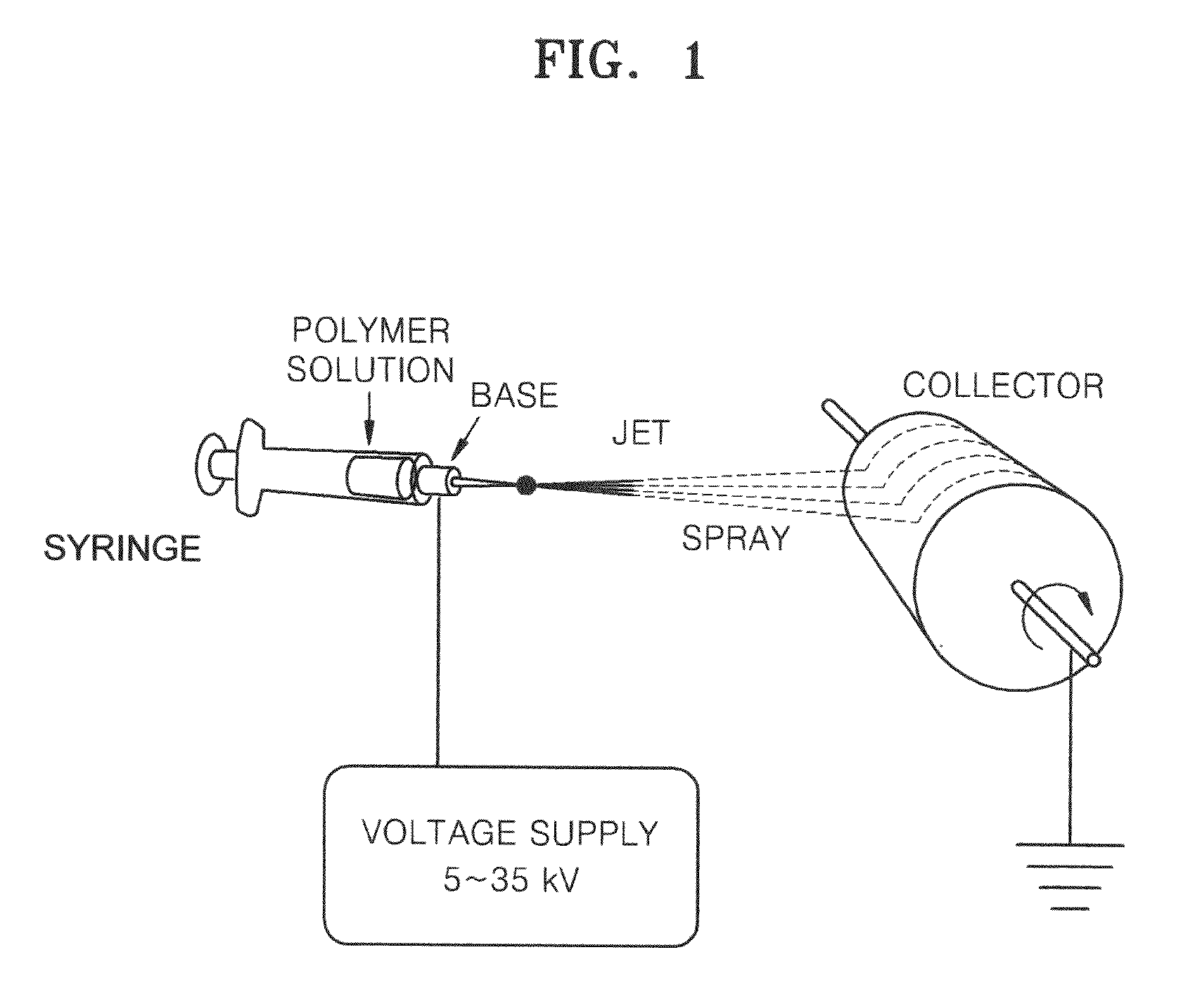
[0100]First, polyacrylonitrile (PAN, Aldrich) was dissolved in N,N-dimethylformamide (DMF, Aldrich) solvent to prepare a 10 wt % solution and the solution was electrospun to prepare a carbon nanofiber precursor in a web form. The solution was electrospinned at a rate of 1 ml / hr, and 20 kV as optimized bias voltage was applied thereto, wherein the distance between electrodes (between a needle and a collector) was 15 cm, and a drum covered with an aluminum foil was used as the collector. The collector was rotated at 100 rpm. The needle had a diameter of 0.1 to 1 mm, and the electrospinning was performed at room temperature (electrospinning operation). FIG. 1 is a schematic diagram illustrating an electrospinning method.

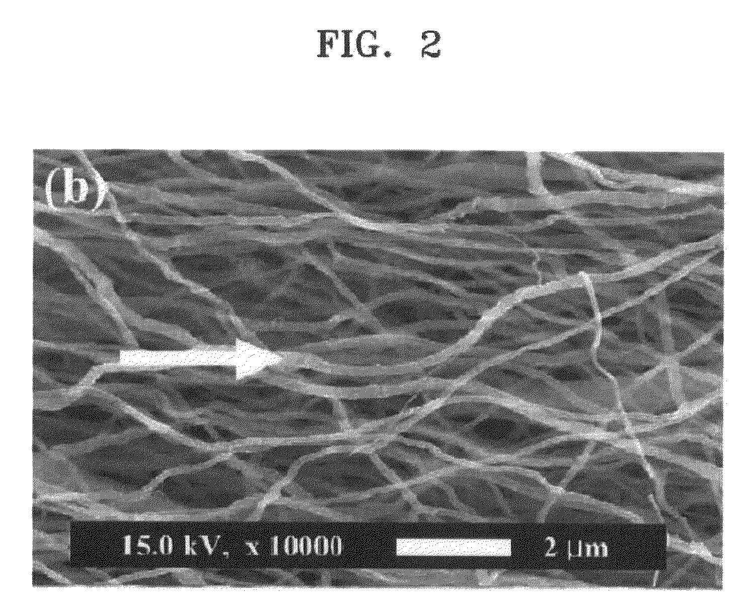
[0101]The electrospun carbon nanofiber precursor in a web form was then stabilized in a furnace with a compressed air supply at 280° C. for 1 hour. A SEM image of the prepared carbon nanofiber is illustrated in FIG. 2.

[0102]The carbon nano...

example 2

Preparation of Nanocomposite

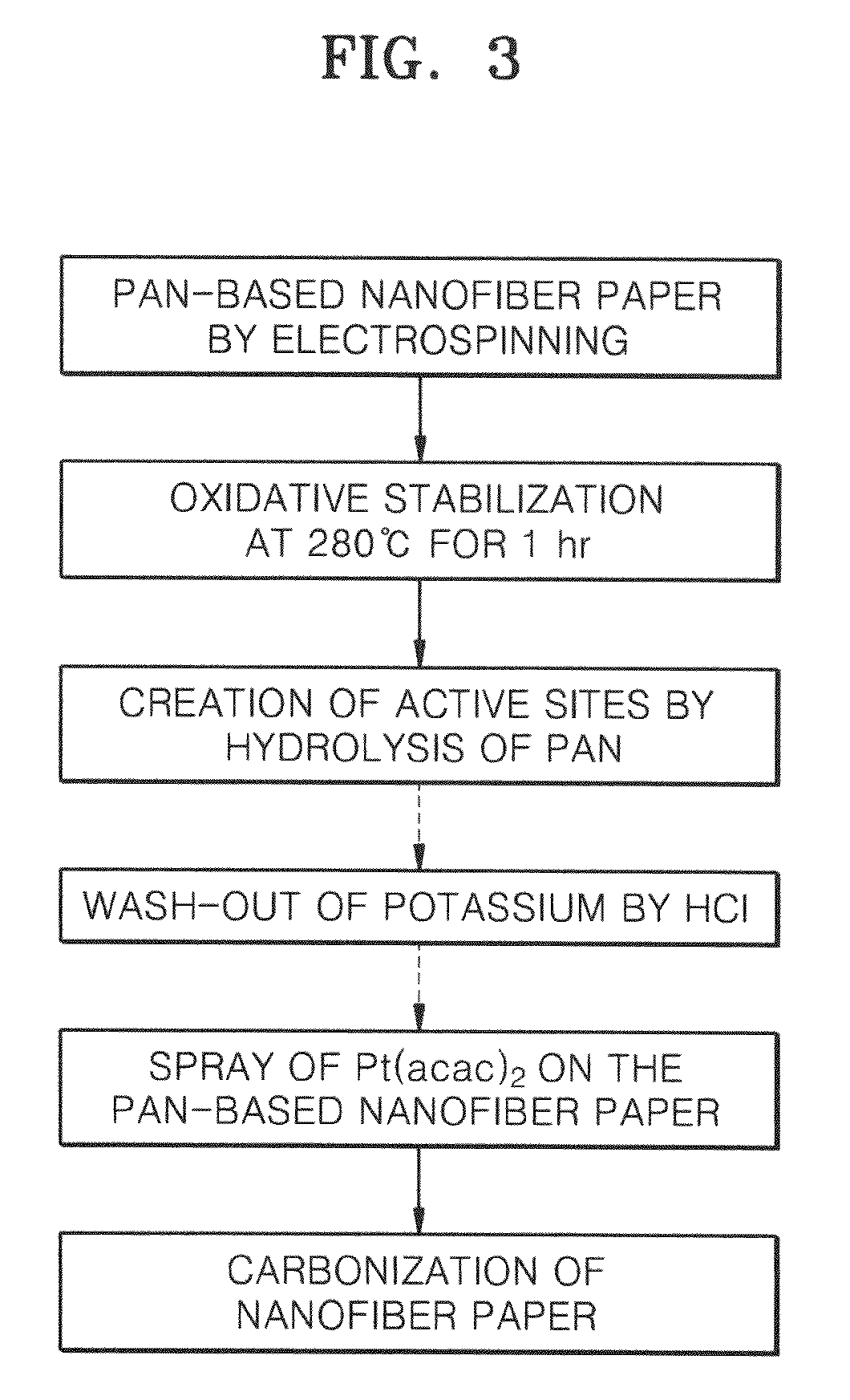
[0104]FIG. 3 is a flowchart illustrating a process for preparing a nanocomposite according to Example 2 of the present invention.

[0105]First, polyacrylonitrile (PAN, Aldrich) was dissolved in N,N-dimethylformamide (DMF, Aldrich) solvent to prepare a 10 wt % solution, and the solution was electrospun to prepare a carbon nanofiber precursor in a web form. The solution was electrospinned at a rate of 1 ml / hr, and 20 kV as optimized bias voltage was applied thereto, wherein the distance between electrodes (between a needle and a collector) was from 10 to 20 cm, and a drum covered with an aluminum foil was used as the collector. The collector was rotated at 100 rpm. The needle had a diameter of 0.1 to 1 mm, and the electrospinning was performed at room temperature (electrospinning operation).

[0106]The electrospun carbon nanofiber precursor in a web form was then stabilized in a furnace with a compressed air supply at 280° C. for 1 hour (stabilization operation...

example 3

[0111]A nanocomposite was prepared in the same manner as in Example 2, except that the carbon nanofiber precursor was immersed in a 0.1 M KOH solution at 30° C. for 2 hours to hydrolyze the surface of the carbon nanofiber precursor.


PUM

PropertyMeasurementUnit
binding energyaaaaaaaaaa

Abstract

Provided is a nanocomposite for the catalyst layer of a fuel cell electrode including: a carbon nanofiber; and metal catalyst particles uniformly applied to the surface of the carbon nanofiber, wherein the carbon nanofiber has a surface oxygen content of at least 0.03 calculated by the formula: Oxygen content=[atomic percentage of oxygen/atomic percentage of carbon] using atomic percentages of oxygen and carbon, respectively calculated from an area of an oxygen peak having a binding energy of 524 to 540 eV, an area of a nitrogen peak having a binding energy of 392 to 404 eV, and an area of a carbon peak having a binding energy of 282 to 290 eV in X-ray photoelectron spectroscopy. The nanocomposite according to the present invention has high surface oxygen content and has metal catalyst nano particles densely and uniformly distributed on the outer wall of the carbon fibers, thereby having high electrochemical efficiency. Thus, efficiency of fuel cells can be improved using the nanocomposite.

Description

CROSS-REFERENCE TO RELATED PATENT APPLICATION[0001]This application claims priority to and the benefit of Korean Patent Application No. 10-2007-0007643, filed on Jan. 24, 2007, in the Korean Intellectual Property Office and Korean Patent Application No. 10-2007-0103168, filed on Oct. 12, 2007, in the Korean Intellectual Property Office the disclosure of which is incorporated herein in its entirety by reference.BACKGROUND OF THE INVENTION[0002]1. Field of the Invention[0003]The present invention relates to a carbon nanofiber for a fuel cell electrode, a nanocomposite for a fuel cell, a method of preparing the carbon nanofiber and the nanocomposite, an electrode including the nanocomposite, and a fuel cell including an electrode having the nanocomposite.[0004]2. Description of the Related Art[0005]Recently, research has been conducted into fuel cells as power sources for vehicles and electronic devices due to increasing concerns regarding environmental problems in burning fossil fuels...

Claims


Application Information

Patent Timeline
Patent Type & Authority Applications(United States)
IPC IPC(8): H01M4/86B29C47/00
CPCB82Y30/00D01F9/20D01F11/04H01M4/90Y10S977/948H01M4/92H01M4/926H01M2008/1095Y02E60/50H01M4/9083
Inventor LEE, JEONG-HEECHOI, JAE-YOUNGPAK, CHAN-HORA, EUN-JULEE, YOUNG-HEEAN, KAY-HYEOK
Owner SAMSUNG SDI CO LTD
Why Eureka
Try Eureka