Lateral Emitting Optical Fiber and Light Emitting Device

a technology of optical fiber and light emitting device, which is applied in the field of optical fiber, can solve the problems of low light transmittance, inability to emit light in a wide visual angle, scattered light which has reached the core-clad boundary, etc., and achieves the effects of reducing ultraviolet transmittance, increasing uniformity of luminance, and reducing ultraviolet transmittan

Inactive Publication Date: 2008-08-07
3M INNOVATIVE PROPERTIES CO
View PDF4 Cites 5 Cited by
  • Summary
  • Abstract
  • Description
  • Claims
  • Application Information

AI Technical Summary

Benefits of technology

[0035]The clad is fabricated, for example, by dispersing zinc oxide particles in a light-transmitting resin and forming resin pellets which are then melted and molded. In order to adjust the zinc oxide particle content in the clad, a resin containing no light-scattering particles may be mixed with the resin pellets. The molding apparatus used may be an extruder, for example. As explained above, the core starting material is injected into the hollow clad obtained in this manner and then polymerized to fabricate the optical fiber. The melted polymer for the clad and the melted polymer for the core may also be subjected to coextrusion molding to form the optical fiber.
[0036]The light-transmitting resin for the clad will generally be a resin material having a lower refractive index than the refractive index of the light-transmitting material for the core, and preferred examples for use are tetrafluoroethylene-hexafluoropropylene copolymer (FEP), tetrafluoroethylene-ethylene copolymer (ETFE) and tetrafluoroethylene-hexafluoropropylene-vinylidene fluoride copolymer (THV).
[0037]So long as the effect of the invention is not hindered, the clad may contain other additives in addition to the aforementioned material. Examples of suitable additives include crosslinking agents, ultraviolet absorbers, heat stabilizers, surfactants, plasticizers, antioxidants, antifungal agents, luminous materials, pressure-sensitive adhesives, tackifiers and the like.
[0038]The clad may have the thickness of ordinary clads used for lateral emitting optical fibers and is not particularly restricted, but the range of 100-800 μm is suitable.
[0039]According to the invention, since the clad contains zinc oxide particles and the particles reduce ultraviolet transmittance, there is no need for a protective layer around the periphery of the clad, and therefore durability can be maintained even with an optical fiber composed only of a core material and clad material. However, an additional layer may still be formed on the outer periphery of the clad if desired.
[0040]The optical fiber of the invention may be suitably utilized as a light-emitting device substituting for a neon light-emitting device. One mode of a light-emitting device according to the invention comprises a lateral emitting optical fiber of the invention and a light source which introduces light from at least one end of the optical fiber. While it is sufficient if the light is introduced from one end of the core, the light source is preferably situated so as to introduce light from both ends of the core. For example, the light source may consist of a first light source which introduces light from one end of the core and a second light source which introduces light from the other end of the core. By thus introducing light from both ends of the core, it is possible to further increase the uniformity of luminance. The same effect can be achieved by using a single light source, and using a separate light propagating means such as different optical fibers, for introduction of light from both ends of the core.

Problems solved by technology

However, the light-diffusing reflection film described above generally has diffusing low light transmittance and cannot emit light in a wide visual angle (such as across the entire periphery) as can be achieved with neon tubes.
However, inclusion such light-scattering particles in the clad causes light which has reached the core-clad boundary to be scattered.
Highly light transmitting acrylic resins are generally known as materials for cores, but such highly transparent resins are susceptible to degradation by ultraviolet sunlight, leading to yellowing and brittleness.
However, since Methods 1 and 2 above increase the number of manufacture steps and amount of material required, they are associated with increased cost.
However, if the titanium oxide content is excessively increased in order to improve the ultraviolet shield factor, light entering into the optical fiber is scattered to an extreme degree so that it leaks out of the clad immediately after entering, making it difficult to achieve uniformity of lateral luminance along the lengthwise direction of the optical fiber.
In addition, excessively increasing the titanium oxide content to improve the ultraviolet shield factor also lowers the visible light transmittance, creating a problematic reduction in the absolute level of lateral luminance.

Method used


Image

  • Lateral Emitting Optical Fiber and Light Emitting Device
  • Lateral Emitting Optical Fiber and Light Emitting Device
  • Lateral Emitting Optical Fiber and Light Emitting Device

Examples


example 1

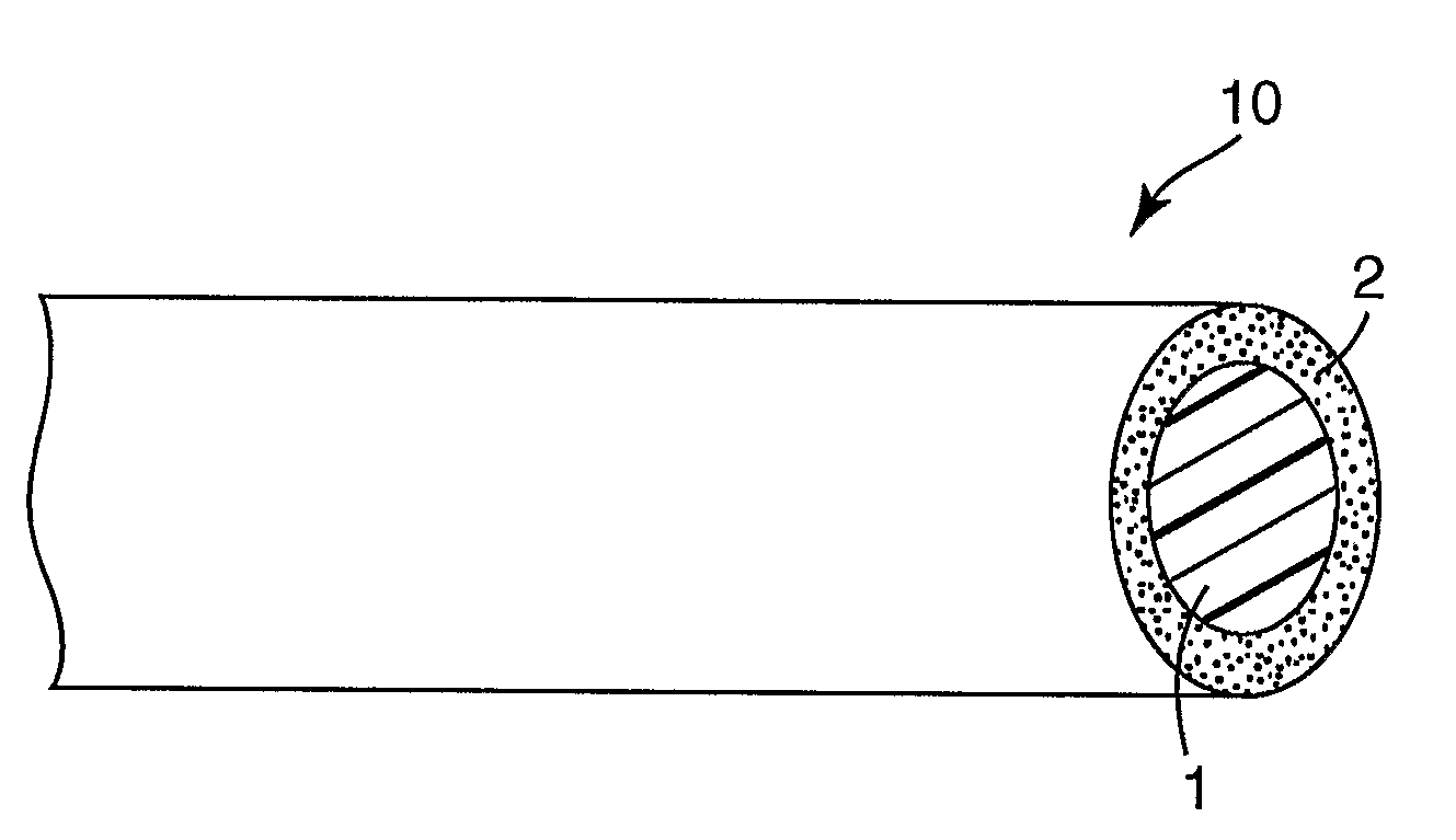
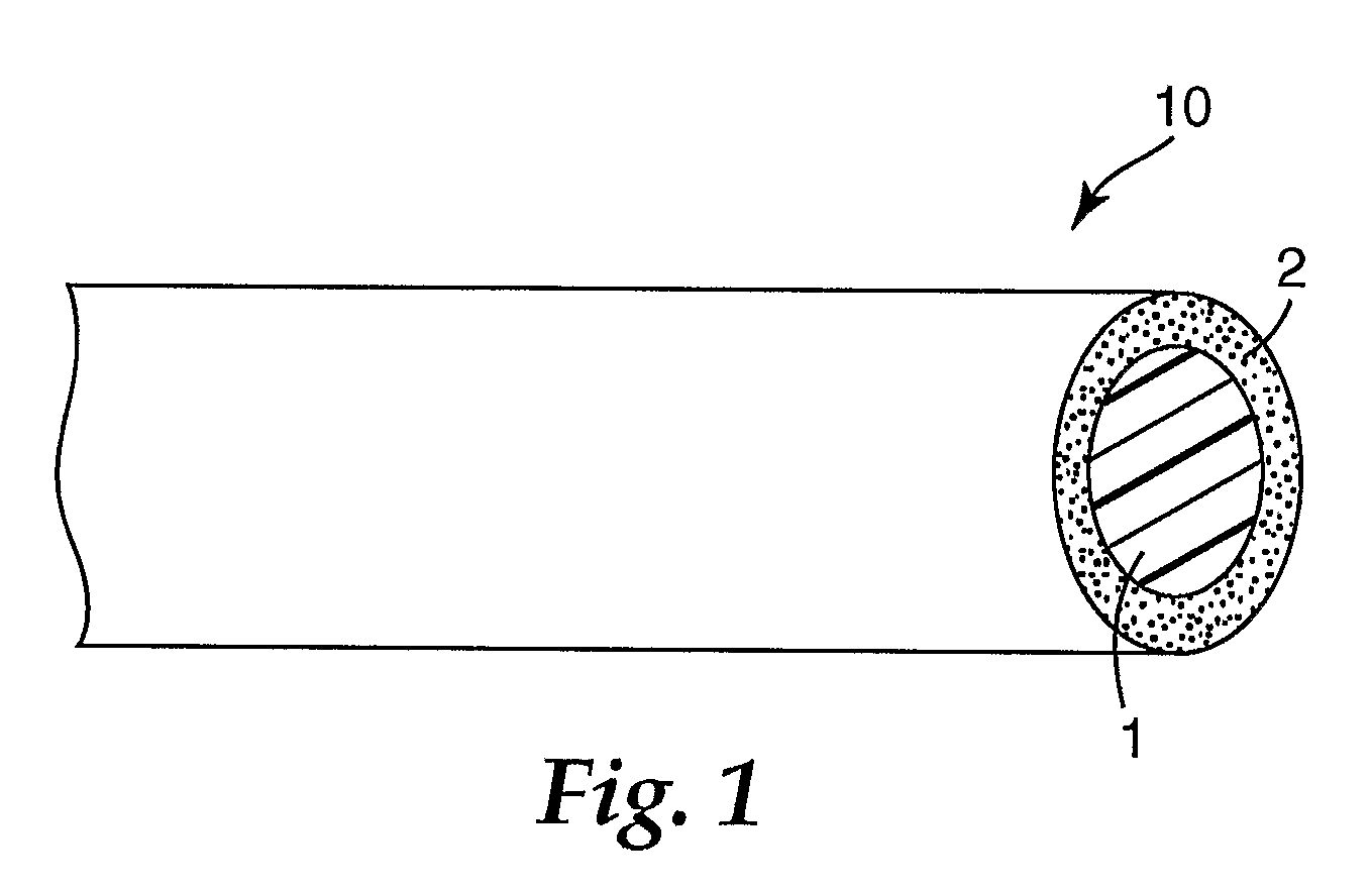
[0043]FEP100J (trade name) (DuPont) was loaded into a first extruder, and then FEP resin comprising zinc oxide particles (particle size=0.5 μm) dispersed therein at 29 wt % was loaded into a second extruder at 5.56 parts by weight with respect to 100 parts by weight of FEP100J (trade name). The resins were coextruded through a prescribed die, to obtain a tube-shaped double-layered clad material with an outer diameter of about 13 mm, comprising a light-transmitting resin layer with a thickness of about 317 μm as an outer layer and a light-dispersing resin layer with a thickness of about 138 μm as an inner layer.

[0044]For formation of the core material, 4 parts by weight of hydroxyethyl methacrylate, 96 parts by weight of n-butyl methacrylate and 1 part by weight of triethyleneglycol dimethacrylate were combined to prepare a monomer mixture. Next, 1.0 part by weight of lauroyl peroxide was added to the mixture as a thermal polymerization initiator to prepare a core precursor.

[0045]Aft...

example 2

[0047]Two extruders including a first extruder and second extruder were prepared, and FEP100J (trade name) (DuPont) was loaded into the first extruder and FEP resin having zinc oxide particles (particle size=0.5 μm) dispersed therein at 29 wt % was loaded into the second extruder at 5.56 parts by weight with respect to 100 parts by weight of FEP100J (trade name). The resins were coextruded through a prescribed die, to obtain a tube-shaped double-layered clad material with an outer diameter of about 13 mm, comprising a light-transmitting resin layer with a thickness of about 244 μm as an outer layer and a light-dispersing resin layer with a thickness of about 256 μm as an inner layer. An optical fiber was fabricated in the same manner as Example 1 except for using this clad material. The final outer diameter of the optical fiber was 13.7 mm, and the clad material thickness was 0.5 mm.

[0048]The 256 μm inner layer portion of the clad material contained zinc oxide particles at 1.53 wt %...

example 3

[0049]Two extruders including a first extruder and second extruder were prepared, and a mixture of 12.5 parts by weight of FEP resin having zinc oxide particles (particle size=0.5 μm) dispersed therein at 29 wt % combined with respect to 100 parts by weight of FEP100J (trade name) was loaded into the first extruder. Also, a mixture of 5.56 parts by weight of FEP resin having zinc oxide particles (particle size=0.5 μm) dispersed therein at 29 wt % combined with respect to 100 parts by weight of FEP100J (trade name) was loaded into the second extruder. The resins were coextruded through a prescribed die, to obtain a tube-shaped double-layered clad material with an outer diameter of about 13 mm, comprising a light-transmitting resin layer with a thickness of about 19 μm as an outer layer and a light-dispersing resin layer with a thickness of about 481 μm as an inner layer. An optical fiber was fabricated in the same manner as Example 1 except for using this clad material. The final out...


PUM

PropertyMeasurementUnit
particle sizesaaaaaaaaaa
particle sizeaaaaaaaaaa
refractive indexaaaaaaaaaa

Abstract

A lateral emitting optical fiber has a core material including a light transmitting resin capable of transmitting light entering from one end to the other end, and a clad material covering the periphery of the core material and having a lower refractive index than the core material, wherein the clad material includes a light transmitting resin and zinc oxide particles dispersed in the light transmitting resin.

Description

TECHNICAL FIELD OF THE INVENTION [0001]The present invention relates to an optical fiber, and more specifically, it relates to a “lateral emitting optical fiber” wherein light introduced from at least one end in the direction of the core length is allowed to leak out through a clad in contact with the periphery (i.e. sides) of the core. The invention further relates to a light emitting device comprising the optical fiber.[0002]BACKGROUND[0003]Typical lateral emitting optical fibers belong to either types having a striped light-scattering reflection film adhering to a portion of the periphery of the core along the lengthwise direction of the core or types wherein a clad in contact with the core periphery includes light-scattering particles and light emitted from the core into the clad is scattered by the clad and leaks out.[0004]The optical fiber of the first aforementioned type comprises, as a light-diffusing reflection film, a coating comprising a light-transmitting resin and light...

Claims


Application Information

Patent Timeline
Patent Type & Authority Applications(United States)
IPC IPC(8): G02B6/02
CPCG02B6/001G02B6/02033G02B6/004G02B6/00G02B6/0001
Inventor IRIE, SHINICHIKOGA, AKIHITO
Owner 3M INNOVATIVE PROPERTIES CO
Why Eureka
Try Eureka