Hydrodynamic cavitation crystallization device and process

a technology of hydrodynamic cavitation and crystallization device, which is applied in the direction of vibration crystallization, crystallization auxiliary selection, separation process, etc., can solve the problems of low purity of materials, reduced stability, and high friability

Inactive Publication Date: 2008-08-14
CAVITECH HLDG
View PDF25 Cites 49 Cited by
  • Summary
  • Abstract
  • Description
  • Claims
  • Application Information

AI Technical Summary

Problems solved by technology

However, the direct crystallization of small sized, high surface area particles is usually accomplished in a high supersaturation environment, which often results in material of low purity, high friability, and decreased stability due to poor crystal structure formation.
Slow crystallization is a common technique used to increase product purity and produce a more stable crystal structure, but it is a process that decreases crystallizer productivity and produces large, low surface area particles that require subsequent high intensity milling.
However, high energy milling has drawbacks.
Milling may result in yield loss, noise and dusting, as well as unwanted personnel exposure to highly potent pharmaceutical compounds.
Also, stresses generated on crystal surfaces during milling can adversely affect labile compounds.
Overall, the three most desirable end-product goals of high surface area, high chemical purity, and high stability cannot be optimized simultaneously using current crystallization technology without high energy milling.
When using current reverse addition technology for direct small particle crystallization, a concentration gradient can not be avoided during initial crystal formation because the introduction of feed solution to anti-solvent in the stirred vessel does not afford a thorough mixing of the two fluids prior to crystal formation.
The existence of concentration gradients, and therefore a heterogeneous fluid environment at the point of initial crystal formation, impedes optimum crystal structure formation and increases impurity entrainment.
Another standard crystallization procedure employs temperature variation of a solution of the material to be crystallized in order to bring the solution to its supersaturation point, but this is a slow process that produces large crystals.
Also, despite the elimination of a solvent gradient with this procedure, the resulting crystal characteristics of size, purity and stability are difficult to control and are inconsistent from batch to batch.
On the other hand, crystallization procedures using hydrodynamic cavitation have not yet been proposed.
As the pressure of the liquid then increases, vapor condensation takes place in the cavities and bubbles, and they collapse, creating very large pressure impulses and very high temperatures.

Method used


Image

  • Hydrodynamic cavitation crystallization device and process
  • Hydrodynamic cavitation crystallization device and process
  • Hydrodynamic cavitation crystallization device and process

Examples


example 1

[0062]30 grams of technical grade NaCl (sodium chloride)-(feed solution) was dissolved into 100 ml of distilled water in a beaker. 200 ml of ethanol (antisolvent) (95% ethanol+5% methanol, Aldrick™) was added to the beaker with a volumetric ratio of anti-solvent / feeding solution=2:1.

[0063]The solution was mixed until NaCl (sodium chloride) crystals appeared. Upon completion, the product was filtered, washed, and then dried. The crystal particle size (d 90) was 150 microns.

example 2

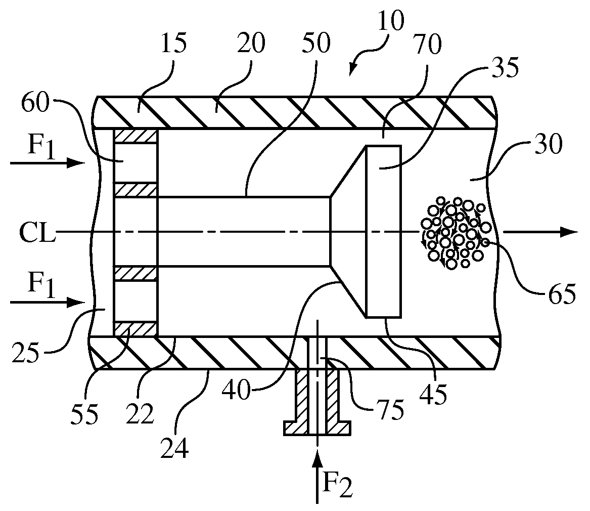
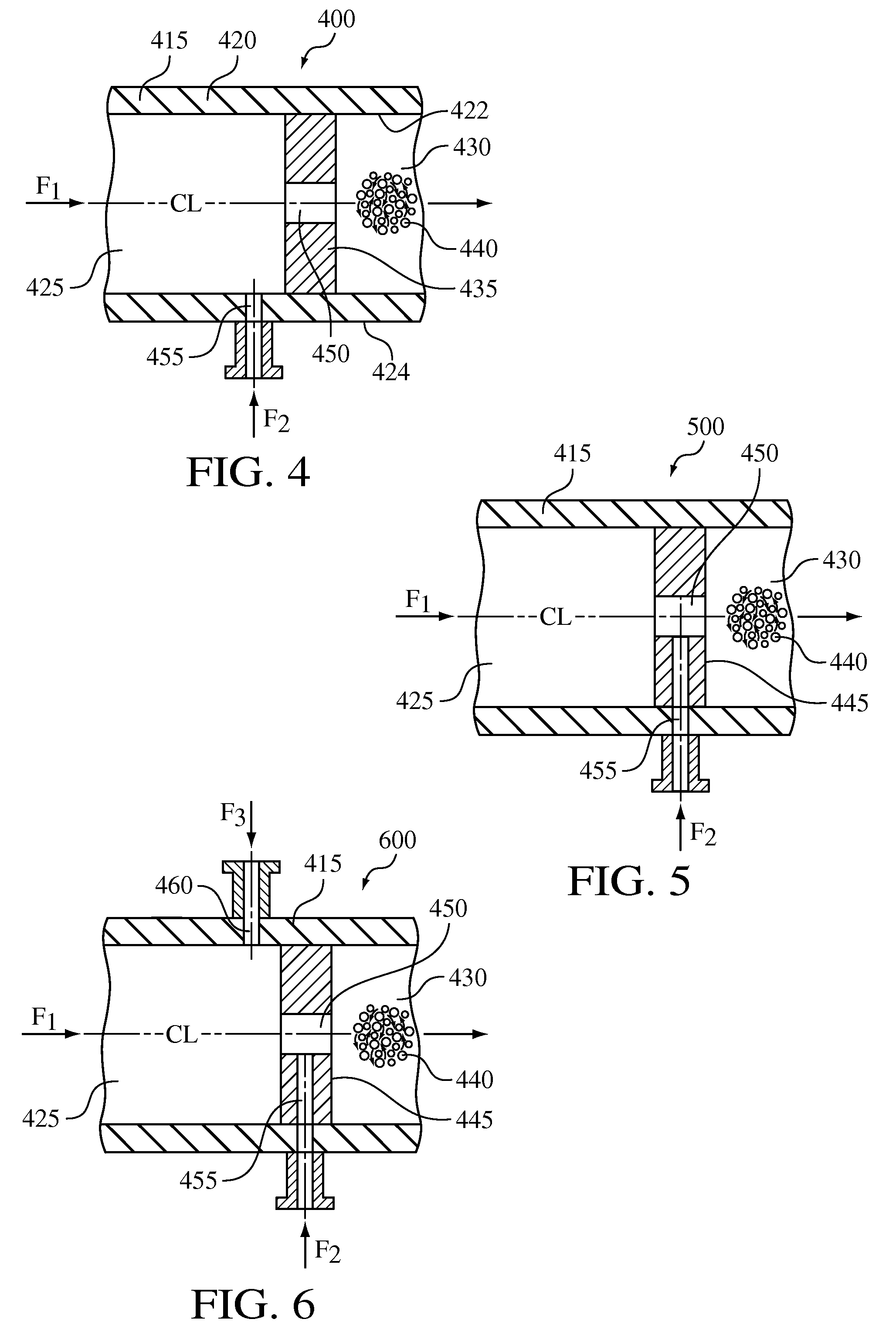
[0064]The crystallization process was carried out in a cavitation device substantially similar to the device 400 illustrated in FIG. 4 and described above. The cavitation device included a single orifice having a diameter of 0.010 inches and was capable of operating at pressures up to 8,000 psi with a nominal flow rate of up to 800 ml / min.

[0065]Ethanol (anti-solvent) was fed at 600 psi, via a high pressure pump, through the flow-through channel, while NaCl (feed solution) was introduced at 600 psi, via a high pressure pump, into flow-through channel via a port positioned upstream from the orifice at a 2:1 anti-solvent / feed solution ratio. The combined anti-solvent and feeding solution then passed through the orifice causing hydrodynamic cavitation to effect nucleation. NaCl was crystallized and discharged from cavitation device. The resultant crystal particle size (d 90) of the recovered crystalline NaCl was 30 microns.

example 3

[0066]The crystallization process of Example 2 was repeated in the cavitation device 400, but at a higher hydrodynamic pressure of 3,000 psi. The resultant crystal particle size (d 90) was 20 microns.


PUM

PropertyMeasurementUnit
temperatureaaaaaaaaaa
crystal particle sizeaaaaaaaaaa
flow rateaaaaaaaaaa

Abstract

A device and process for crystallizing a compound using hydrodynamic cavitation comprising the steps of mixing at least one stream of a solution of such compound to be crystallized with at least one stream of an anti-solvent and passing the mixed streams at an elevated pressure through a local constriction of flow to create hydrodynamic cavitation thereby causing nucleation and the direct production of crystals. The compound to be crystallized can be, for example, an active pharmaceutical ingredient.

Description

CROSS-REFERENCE TO RELATED APPLICATIONS[0001]This application is a continuation-in-part of U.S. application Ser. No. 11 / 330,473 filed on Jan. 12, 2006, which is a divisional of U.S. application Ser. No. 10 / 382,117 filed on Mar. 4, 2003, which is now U.S. Pat. No. 7,041,144.BACKGROUND OF THE INVENTION[0002]The present application relates to a device and process for crystallizing compounds using hydrodynamic cavitation.[0003]The types of compounds that may be crystallized utilizing the devices and methods described herein include pharmaceutical compounds as well as any other compounds used in industry. Crystallization from solution of pharmaceutically active compounds or their intermediates is the typical method of purification used in industry. The integrity of the crystal structure, or crystal habit, that is produced and the particle size of the end product are important considerations in the crystallization process.[0004]High bioavailability and short dissolution time are desirable...

Claims


Application Information

Patent Timeline
Patent Type & Authority Applications(United States)
IPC IPC(8): C01D3/04C07C62/06
CPCB01D9/005B01D9/0054B01D9/0081B01F5/0451B01F5/0656C30B7/00C30B29/54C30B7/10C30B29/12B01D9/0063B01F25/3131B01F25/434
Inventor KOZYUK, OLEG V.
Owner CAVITECH HLDG
Why Eureka
Try Eureka