SEPARATION OF AQUEOUS AMMONIA COMPONENTS FOR NOx REDUCTION

a technology of ammonia and nox, which is applied in the direction of separation processes, liquid degasification, evaporation, etc., can solve the problems of ammonia contamination of the steam system, the need for maintenance of the electric or steam coil, and the long time required in the hot region, so as to achieve energy efficiency and generate steam more economically.

Inactive Publication Date: 2008-08-21
HITACHI POWER SYST AMERICA
View PDF31 Cites 18 Cited by
  • Summary
  • Abstract
  • Description
  • Claims
  • Application Information

AI Technical Summary

Benefits of technology

[0012]In one exemplary embodiment, the apparatus comprises a stripper that is used to produce a first ammonia vapor and a first aqueous ammonia solution from a second aqueous ammonia solution from a reflux tank. The stripper does this by spraying the second aqueous solution down a structure through rising steam, causing separation of the second aqueous solution into the first aqueous solution and the first ammonia vapor. In some exemplary embodiments the apparatus also includes a reflux tank that is used to produce a second ammonia vapor and the second aqueous ammonia solution from the first ammonia vapor and liquid aqueous ammonia which serves as an input to the reflux tank. In the exemplary embodiment, the reflux tank generates and outputs the second ammonia vapor for introduction into the flue gas. Also, the first aqueous ammonia solution which has been heated, e.g., by steam, can be used to heat two heat exchangers, which are used respectively to heat incoming aqueous ammonia, e.g., liquid aqueous ammonia, to the apparatus, and to heat the second ammonia vapor before it is introduced into the flue gas, both processes aiding in the removal of water from the ammonia vapor.
[0013]By using multiple tanks and by using the first aqueous ammonia solution as the heat source for heating other elements of the system, energy efficiency can be achieved while producing ammonia vapor with relatively low concentrations of water included in the vapor and waste water with low concentrations of ammonia.
[0014]In some embodiments of the present invention, the flue gas is monitored for such attributes as NOX concentrations, flow rate, and temperature. Based on the information obtained from the monitoring, one or more control modules control the amount of vaporized ammonia injected into the flue gas stream.
[0015]In various embodiments of the present invention, a condenser is used to condense water out of the first ammonia vapor before it is introduced into the reflux tank.
[0016]To generate the steam used in the apparatus of the invention, a boiler can be placed in the furnace which is generating the flue gas, in order to more economically generate steam to be introduced into the stripper. In this manner, the heat from the furnace can be used to generate steam used to provide the heat used to generate the ammonia vapor injected into the flue gas.
[0017]Additional features and benefits of the present invention are discussed in the detailed description which follows.

Problems solved by technology

This gas may contain components which are harmful to the environment, such as oxides of nitrogen (NOX).
A disadvantage of such a system is the need for maintenance of the electric or steam coils as they are in direct contact with the anhydrous ammonia.
Further, any breach of the steam coil could result in ammonia contamination of the steam system.
A major problem associated with this method of relying on the flue gas to supply the heat is that a long time is required in the hot region in order to vaporize the water and ammonia and for the reaction with the NOX.
A problem with this approach is that everything that the flue gas comes in contact with is contaminated, from such contaminates in the flue gas as dust, ash, and sulfur oxides.
In addition, the amount of heat available for vaporization is a function of the flue gas temperature making control of vaporization more difficult than where the heat source can be readily controlled to supply differing amounts of heat depending on sensed operating conditions.
An undesirable byproduct of some systems is waste water which includes significant amounts of ammonia.
From a cost and environmental standpoint high concentrations of ammonia in waste water can be undesirable.
In addition, waste water with high ammonia concentrations can be harmful is discharged into the environment.
Such treatment can be costly.

Method used


Image

  • SEPARATION OF AQUEOUS AMMONIA COMPONENTS FOR NOx REDUCTION
  • SEPARATION OF AQUEOUS AMMONIA COMPONENTS FOR NOx REDUCTION
  • SEPARATION OF AQUEOUS AMMONIA COMPONENTS FOR NOx REDUCTION

Examples


Embodiment Construction

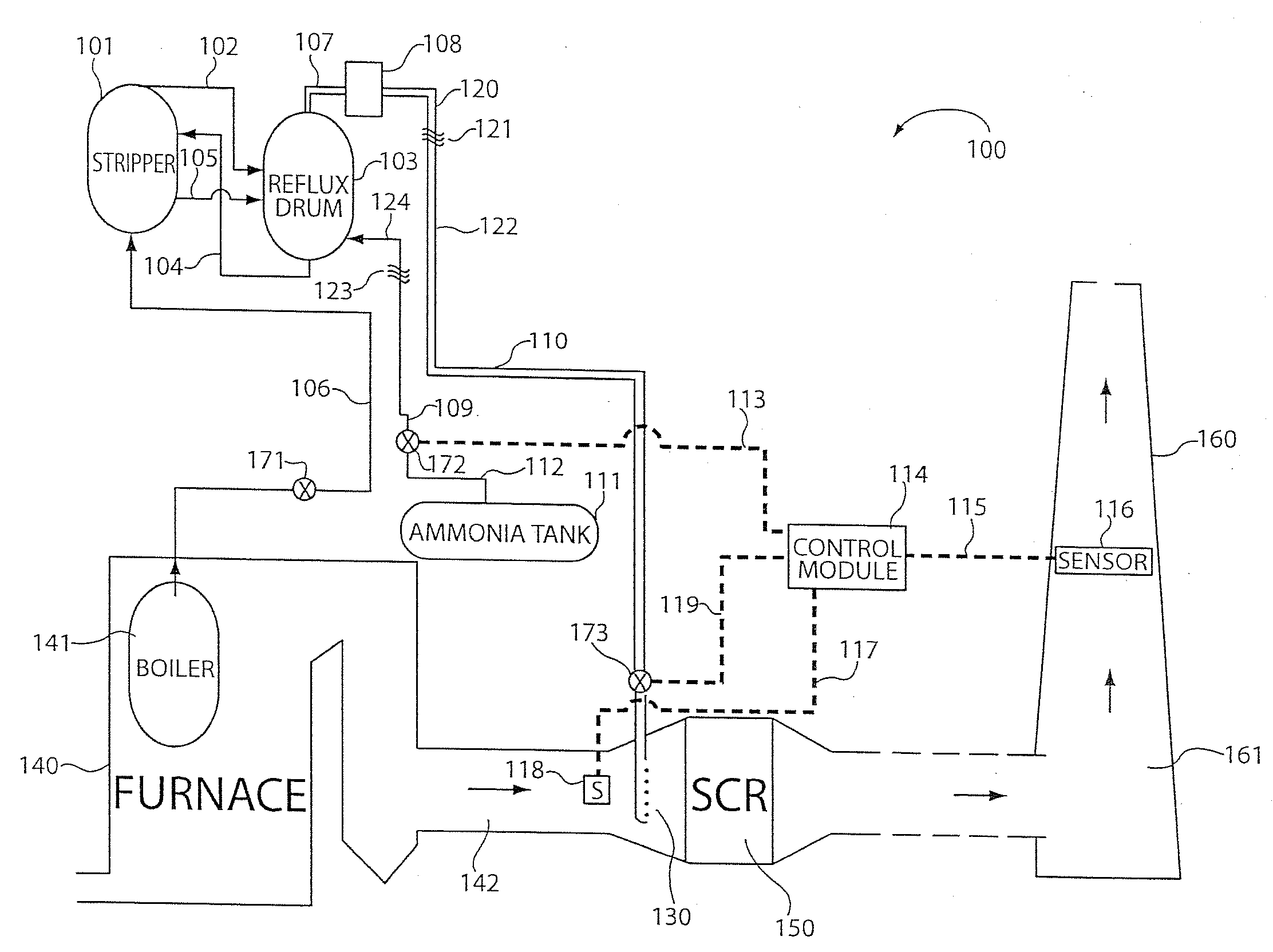
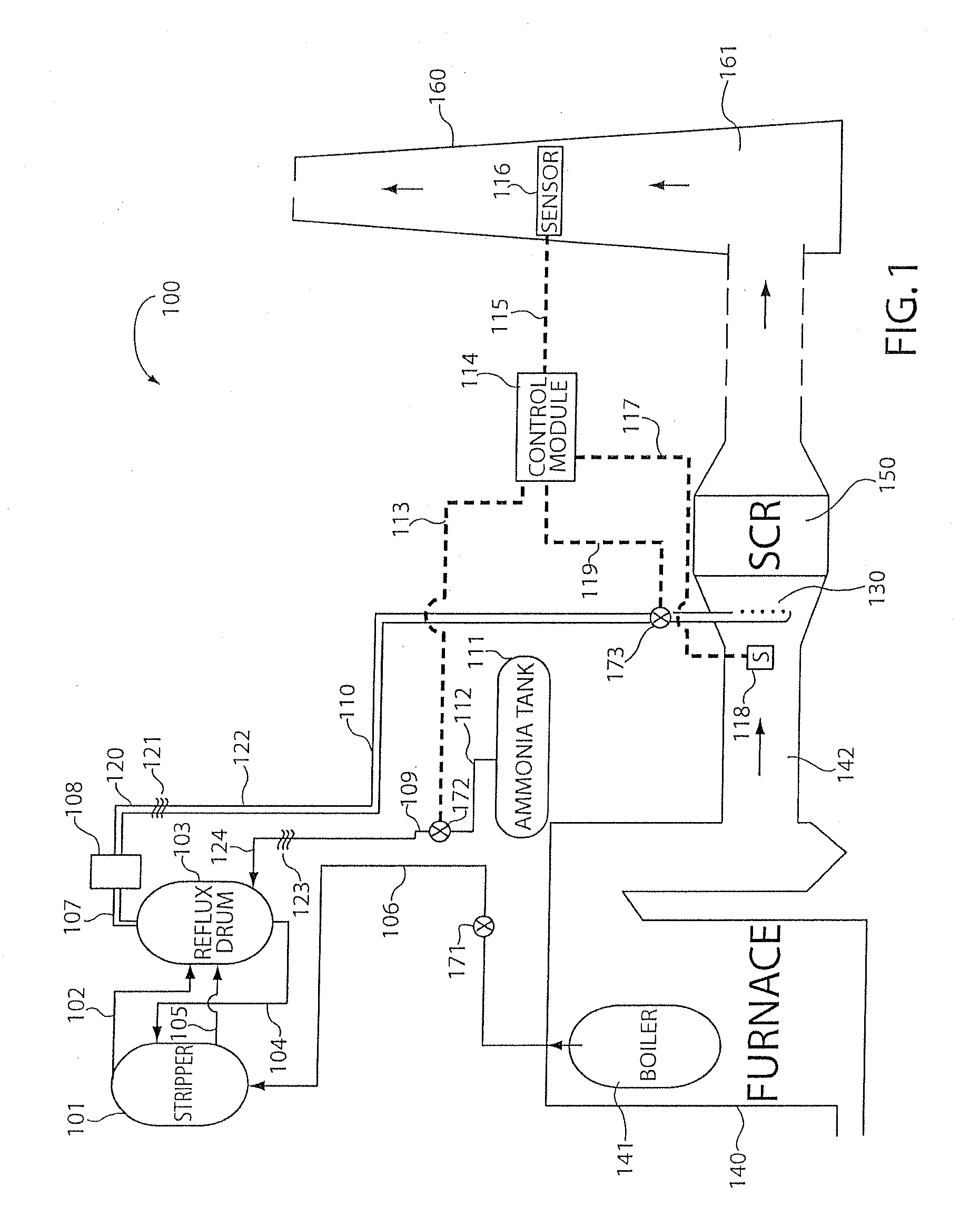
[0023]The methods and apparatus of the present invention for vaporizing ammonia and injecting the vapor into a flue gas stream can be used with a wide range of furnace environments. For example, the invention can be used with power plants, refineries, or other instances of the use of turbine engines, heaters, steam boilers, etc. The invention removes substantially all water from vaporized ammonia for injection into flue gas. This reduced water content makes it easier to vaporize the ammonia (less heat is required than would be required to vaporize water), and the lower water content in the ammonia vapor reduces contamination and sedimentary buildups in the flue and associated equipment. Also, the liquid solution formed as a result of the inventive process is substantially free of ammonia, allowing it to be used as ordinary water in other parts of the plant, or for other purposes, and reducing the expense of treating and disposing of water with an otherwise higher concentration of am...


PUM

PropertyMeasurementUnit
heataaaaaaaaaa
concentrationaaaaaaaaaa
massaaaaaaaaaa

Abstract

Methods and apparatus for generating a vapor to be injected into a flue gas stream are described. Apparatus comprises a fluid vaporization and injection assembly further comprising: a stripper for producing first ammonia vapor and a first aqueous ammonia solution from a second aqueous ammonia solution; a reflux tank for producing a second ammonia vapor and the second aqueous ammonia solution from the first ammonia vapor and the first aqueous ammonia solution; and a first outlet for outputting the second ammonia vapor for introduction into the flue gas.

Description

RELATED APPLICATIONS[0001]The present application describes subject matter which is related to, and or can be used with, the subject matter described in U.S. patent application Ser. No. ______, filed on the same date as the present application and titled “AMMONIA VAPORIZATION SYSTEM USING NON-FLUE GAS INTERMEDIATE HEAT TRANSFER MEDIUM” which names the same inventors as the present application and which is hereby expressly incorporated by reference.FIELD OF THE INVENTION[0002]This invention relates to vaporization systems including, for example, ammonia vaporization systems used for injection of ammonia into flue gas streams.BACKGROUND OF INVENTION[0003]One of the byproducts of power plants and turbine engines is exhaust gas, commonly known as flue gas. This gas may contain components which are harmful to the environment, such as oxides of nitrogen (NOX). The production of NOX can occur when fossil fuels are combusted, such as in turbines, refinery heaters, steam boilers, etc. Such f...

Claims


Application Information

Patent Timeline
Patent Type & Authority Applications(United States)
IPC IPC(8): B01D1/00
CPCB01D1/16B01D3/38B01D53/8625C01C1/10B01D2251/2062B01D2259/124B01D53/90
Inventor GRETTA, WILLIAMPEAR, ERICKARMARKAR, DILEEP
Owner HITACHI POWER SYST AMERICA
Why Eureka
Try Eureka