
Miniature Lamellar Grating Interferometer Based on Silicon Technology

a technology of silicon technology and lamellar grating, applied in the field of lamellar grating interferometer, can solve the problems of large size, high cost, and drawbacks of mems spectrometer, and achieve the effect of high reliability and enhanced miniaturisation

Inactive Publication Date: 2008-08-28
CARAG AG
View PDF2 Cites 18 Cited by
  • Summary
  • Abstract
  • Description
  • Claims
  • Application Information

AI Technical Summary

Benefits of technology

[0005]The object of the present invention is therefore to provide an improved spectrometer element allowing enhanced miniaturisation at high reliability.
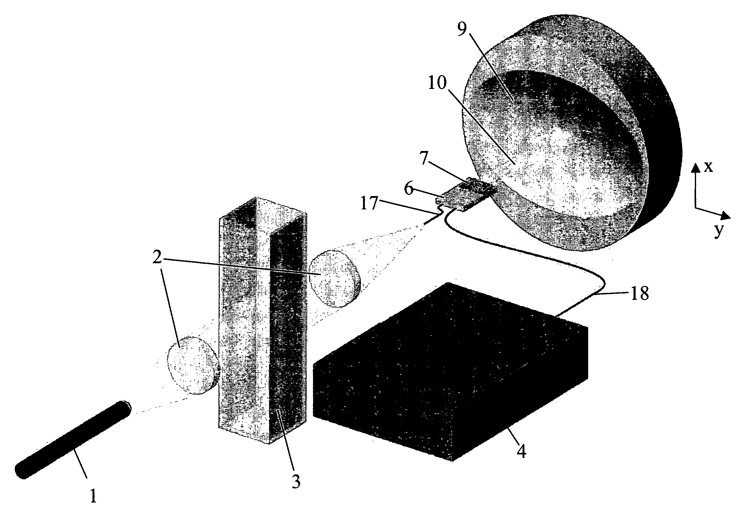
[0006]The present invention proposes a lamellar grating interferometer comprising first means for collimating a light beam and second means for focusing a light beam onto the grating. This particularly simple but highly effective structure of the optical path in conjunction with the use of a micro electromechanical lamellar grating interferometer makes it possible to have very small components which are rugged and very reliable as well as very precise in terms of available spectroscopic resolution. Data-processing of the signal determined in such a lamellar grating interferometer is based on standard Fourier transform techniques.
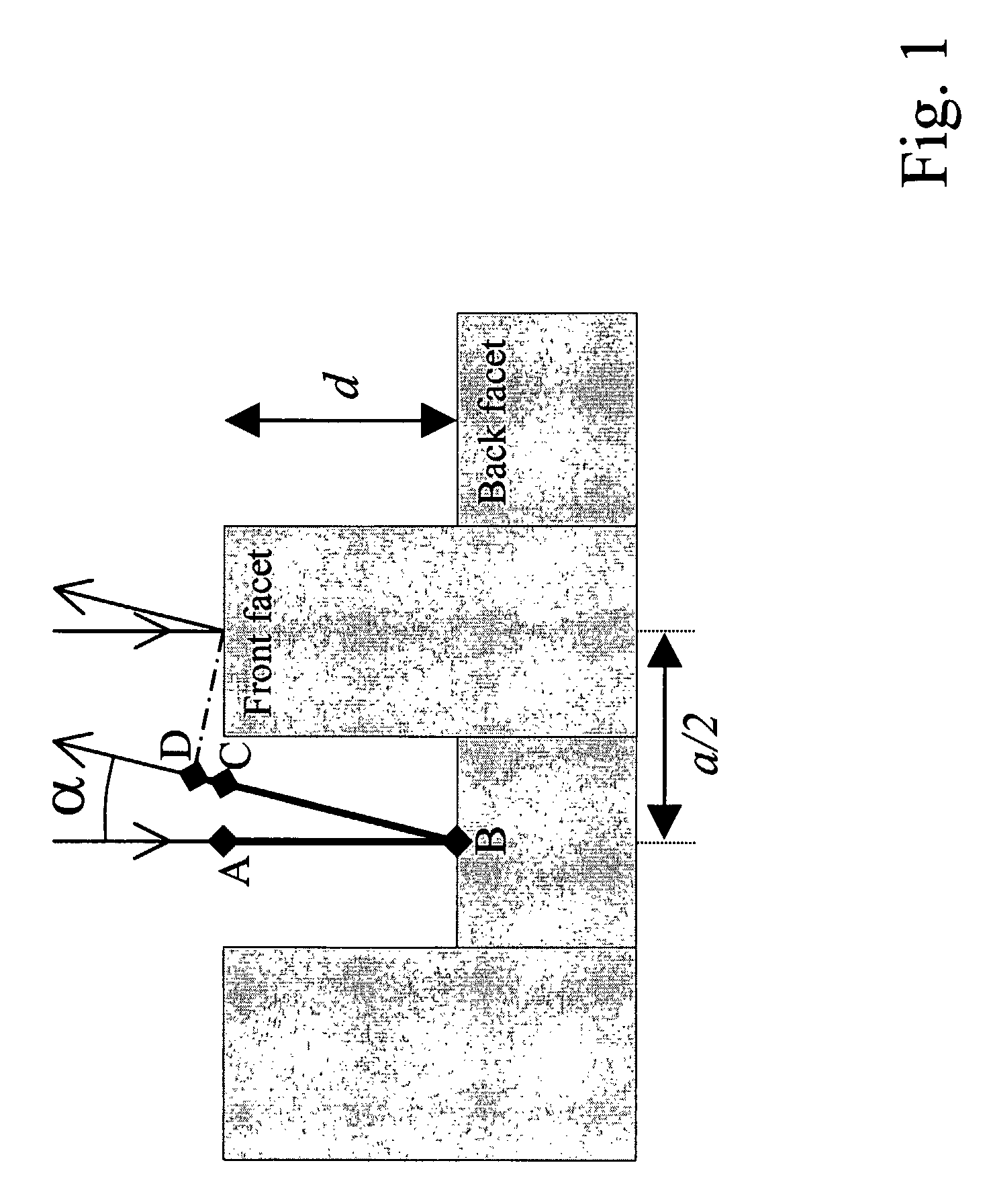
[0016]A very compact design is possible, if according to another embodiment, the moveable reflection elements of the grating are provided in the form of a fork, which is driven based on electrostatic forces, and wherein said fork preferably has a mass in the range of 10−4-10−6 kg. The driving by means of electrostatic forces is preferentially realised by additional, interlocking forks which also form part of the MEMS-device, wherein these interlocking forks are driven by a potential difference provided between these interlocking forks.
[0017]A very high spectroscopic sensitivity and resolution can be realised if, according to another, and particularly preferred embodiment, the fork is driven such as to oscillate substantially with its resonance frequency. To this end, the fork is suspended such as to be freely movable against a mechanical restoring force, which is adapted based on the design and the structure of the MEMS-block. For optimum conditions for the spectroscopic range and the general dimensions being of main interest here, the fork is freely suspended with a force constant in the range of 0.1-1000 N / m. Typically, the MEMS block is machined such as to lead to a resonance frequency of the fork in the range of 100-400 Hz, preferably in the range of 150 to 250 Hz. The high-frequency resonant mode of operation allows high sensitivity and resolution due to the enhanced stability of the displacement (inherent adjustment) and due to the possible signal averaging enabling high signal-to-noise ratios.

Problems solved by technology

However, commonly used FT spectrometers require a high-precision mirror scanning mechanism, resulting in large size and high cost.
For spectroscopic applications MEMS technology has already been used in the context of Michelson interferometers, however in view of miniaturisation and in view of having as little optical components as possible, this type of MEMS spectrometers has its drawbacks.
Nevertheless, stationary FT spectrometers have poor resolution and do not benefit entirely from the throughput advantage.

Method used


Image

  • Miniature Lamellar Grating Interferometer Based on Silicon Technology
  • Miniature Lamellar Grating Interferometer Based on Silicon Technology
  • Miniature Lamellar Grating Interferometer Based on Silicon Technology

Examples


Embodiment Construction

[0042]We present a lamellar grating interferometer realized with MEMS technology. It is used as time-scanning Fourier transform spectrometer. The motion is carried out by an electrostatic comb drive actuator fabricated by silicon micromachining, particularly by silicon-on-insulator technology. For the first time, we have measured the spectrum of an extended white light source with a resolution of 1.6 nm or in a second measurement of 0.5 nm at a wavelength of 400 nm, and of 5.5 nm and of 1.7 nm, respectively at 800 nm. The wavelength accuracy is better than 0.5 nm and the inspected wavelength range extends from 380 nm to 1100 nm of from 300-2600 nm, respectively. The optical path difference maximum is 145 μm or it is 500 μm in the second case. The dimension of the device is 5 mm×5 mm. or 7 mm×5 mm in the second case.

[0043]Spectrometry is widely used in industry and research labs. The methods are as many as different and are used in a variety of fields. In particular, Fourier transfor...


PUM


Abstract

A lamellar grating interferometer is described, in which the light beams are collimated and focused onto the grating by means of mirror 9, which at the same time serves for collecting the light reflected from the grating. In this case, the light beam of a white light source 1 is first collimated by means of first lens 2, and subsequently passed through a sample cuvette 3. The transmitted light beam is subsequentlyy focused and coupled by another lens 2 into a fibre 17. The light to this fibre 17 is subsequentlyy directed towards a mirror 9, reflected from this mirror 9 onto a grating 11, which forms part of a lamellar grating interferometer which is realised by means of a micro electro mechanical device MEMS 7, which is mounted on a MEMS holder 6, as is the fibre 17. The light reflected from this grating 11 is reflected onto the same mirror 9, and focused and coupled by this same mirror 9 into a second multimode fibre 18, which is also fastened to the holder 6. The light guided by this second multimode fibre 18 is subsequently fed into a detection device 4.

Description

TECHNICAL FIELD[0001]The present invention relates to a lamellar grating interferometer, in particular to a lamellar grating interferometer in the form of a microelectromechanical device, i.e. realized with MEMS technology.BACKGROUND OF THE INVENTION[0002]Micro-Electro-Mechanical Systems (MEMS) stands for the integration of mechanical elements, sensors, actuators, and electronics on a common silicon substrate through microfabrication technology. While the electronics are fabricated using integrated circuit (IC) process sequences (e.g., CMOS, Bipolar, or BICMOS processes), the micromechanical components are fabricated using compatible “micromachining” processes that selectively etch away parts of the silicon wafer or add new structural layers to form the mechanical and electromechanical devices.[0003]Fourier transform (FT) spectroscopy is a well-known technique for measuring the spectra of weak extended sources. It offers distinct throughput and multiplexing advantages, which provide...

Claims


Application Information

Patent Timeline
IPC IPC(8): G02B27/44G01B9/02G01J3/453
CPCG01J3/4532G01B9/02007G01B9/02051
Inventor MANZARDO, OMARSCHADELIN, FELIXHERZIG, HANS PETERNOELL, WILFRIEDDE ROOIJ, NICOLAASBUHLER, STEEVEMEIER, CHRISTOPH
Owner CARAG AG
Learn More